Inside electrical enclosure, Inside heater enclosure – Super Systems HP15 User Manual
Page 5
HP 15 Manual Rev A
Page 5 of 5
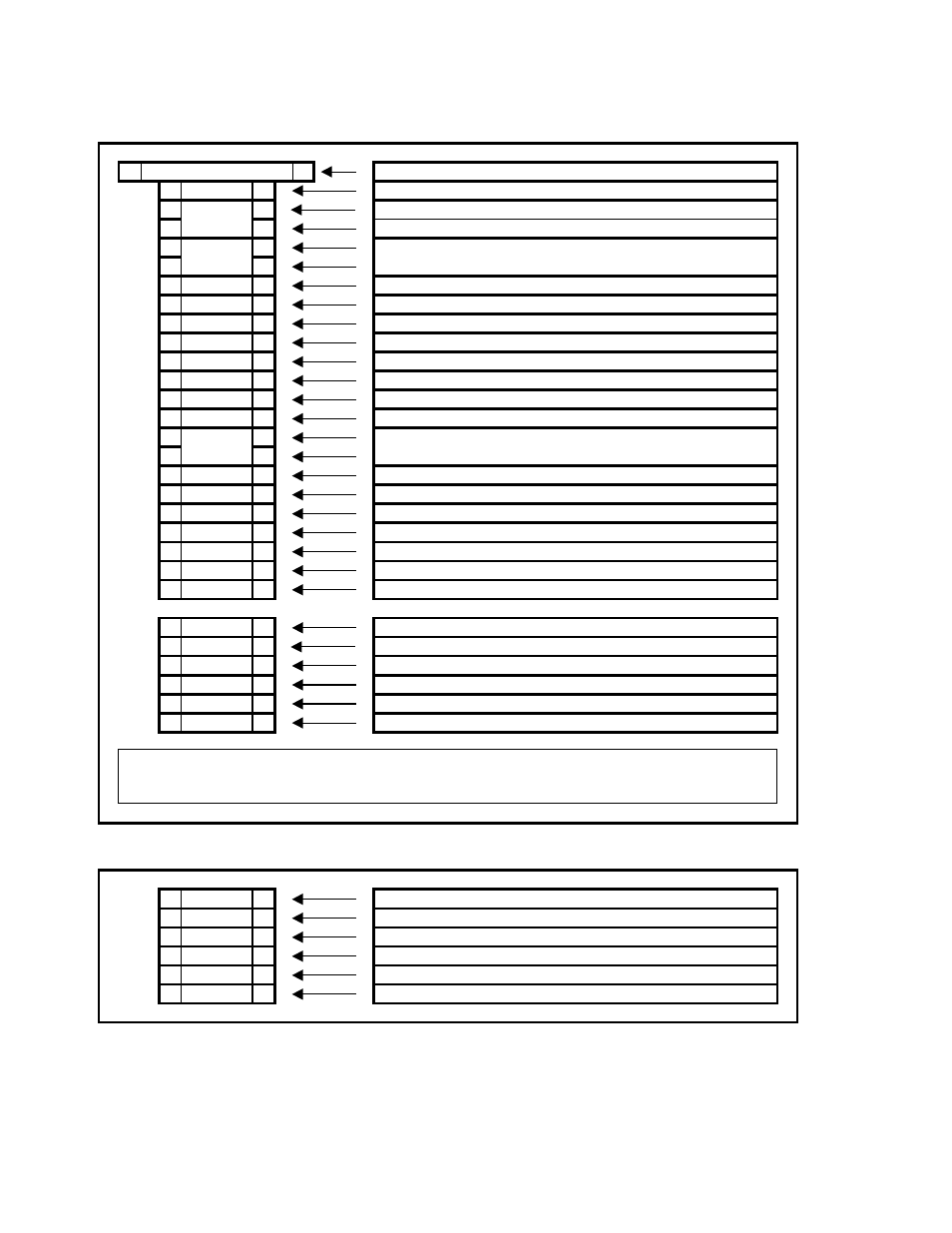
Inside Electrical Enclosure
;
6.0 AMP
;
6 Amp Circuit Breaker
;
1000
;
Incoming Customer 110VAC (Line)
;
;
Incoming Customer 110VAC (Neutral)
;
;
110VAC (Neutral) To Heater
;
;
;
;
;
1103
;
110VAC (Switched Line) to Heater Enclosure
;
1601
;
Enriching Gas Contact #1
;
1602
;
Enriching Gas Contact #2
;
1621
;
Dilution Air Contact #1
;
1622
;
Dilution Air Contact #2
;
1681
;
Alarm Contact #1
;
1682
;
Alarm Contact #2
;
1060
;
24VDC (Negative)
;
;
;
;
;
1320
;
Dry Contact for Sample Inhibit
;
1330
;
Dry Contact for Probe Burn-Off
;
1340
;
Dry Contact Common
;
1641
;
Pump Terminal
;
1002
;
110VAC (Neutral) - Spare
;
GND
;
Incoming Customer 110VAC (Ground)
;
;
;
1021
;
RS485 Host Communications Shield
;
1031
;
RS485 Host Communications RT- (Negative)
;
1041
;
RS485 Host Communications RT+ (Positive)
;
1350
;
Analog Output Common (Positive)
;
1360
;
Analog Output #1 (Negative)
;
1380
;
Analog Output #2 (Negative)
Inside Heater Enclosure
;
1003
;
Incoming 110VAC (Line) from Electrical Enclosure
;
1002
;
Incoming 110VAC (Neutral) from Electrical Enclosure
;
1103
;
Incoming 110VAC (Switched Line) from Electrical Enclosure
;
;
;
;
;
;
110VAC (Line) to Heater Enclosure
24VDC (Positive)
1002
1003
1070
Host Communications connect to the Host Computer.
Analog Output #1 is the 4-20mA signal for Process Variable Retransmission.
Analog Output #2 is the 4-20mA signal for Temperature Control (Optional).