4 analog output wiring – Tecfluid MX4 For FLOMAT Series User Manual
Page 19
19
Terminal
1 Contact
2 Contact
These terminals correspond to an input that resets the value of the totalizer. A potential
free normally open push button can be connected. The push button contact must be a
good quality snap action switch to guarantee correct working at low voltages and reduce
contact bounce effects.
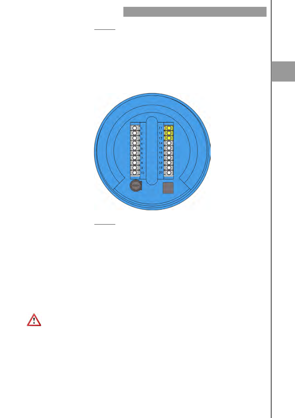
2.2.4 Analog
output
wiring
Terminal
11
mA (positive, active output)
12 mA
13
mA (negative, passive output)
The analog output is galvanically isolated. It can be either active (which means that the
receiving device must be passive) or passive (which means that the receiver must supply
the power for the current loop). It is recommended to use a receptor with an input
resistance of less than 700
Ω to guarantee correct operation.
The configuration of the analog output mode (active or passive) is done by means of the
connection to the terminal strip. For active mode, terminals 11 and 12 are connected. For
passive mode, terminals 12 and 13 are connected.
NOTE: The analog output has protection against reversed polarity. Due to another
protection against over voltages, if a loop supply voltage of more than 32 V is connected
the equipment may be damaged.
2
INSTALLATION OF THE ELECTRONIC CONVERTER