Bd a e c – AEC VacTrac Series Conveying Systems User Manual
Page 28
Advertising
Page 28
VacTrac™ Series Conveying Systems
WH2-605A.4
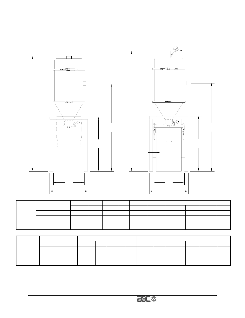
Mechanical Components
Figure 12
VacTrac VFC Vortex Filter Chamber Specifications and Dimensions
B
D
A
E
C
B
C
D
A
E
Blowback
solenoid
Optional
integral
dust can
Floor
A
B
C
D
E
stand
inches
cm
inches cm
inches
cm
inches
cm
inches
cm
29” (74 cm) stand
20”
51
62
7
/
8
”
160
45
1
/
4
”
115
17
1
/
2
”
43
29”
77
VFC-225
Optional 45” (114
cm) stand with
drum
28”
71
78
7
/
8
”
200
60
7
/
8
”
155
25
1
/
2
”
65
45”
114
Floor
A
B
C
D
E
stand
Inches
cm
inches
cm inches
cm
inches
cm
inches
cm
29” (74 cm) stand
20”
51
62
7
/
8
”
160
45
1
/
4
”
115
17
1
/
2
”
43
29”
77
VFC-1000
Optional 45” (114
cm) stand with
drum
28”
71
78
7
/
8
”
200
60
7
/
8
”
155
25
1
/
2
”
65
45”
114
Note: Dimensions are approximate and subject to change without
notice.
Advertising