System configuration – AEC FSS Series 1.5- 10 HP Fountain Solution Systems User Manual
Page 32
FSS Series Fountain Solution Systems
Page 31
IAE-600
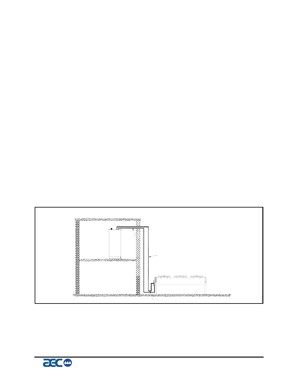
System Configuration
The system can be configured in any of the arrangements shown in
Figures 7, 8 and 9. The configuration and distance between them
effects pipe size, refrigerant charge, oil return, and oil charge.
Therefore, there are limitations that must be adhered to for reliable
and optimal operation.
The limitations are as follows:
1. Leaving water temperature effects discharge line size,
be sure to inform the installing contractor of the leaving
water temperature range that the chiller will be
operating.
2. The total distance between the FSS-R Series circulator
and condenser must not exceed 200 feet or 300
equivalent pipe feet.
3. Liquid line risers must not exceed 15 feet from the base
of the air-cooled condenser (See figure 20).
4. Discharge line risers cannot exceed an elevation
difference greater than 100 feet without a 2% efficiency
decrease.
5. Refer to Figures 7, 8, and 9 for the location of traps.
6. Refrigeration lines must not be crossed. (i.e. chiller
liquid lines are to be piped to condenser liquid lines etc.)
7. Discharge lines should pitch downward, in the direction
of flow, at a rate of ½” per 10 feet of horizontal run. It
should be sized based upon velocity needed for
sufficient oil return.
Figure 7
(Figure 7 – Remote Condenser Piping Trap Locations)
Liquid line riser should not exceed 15 feet from base of air-cooled condenser.
LIQUID LINE
TRAP
DISCHARGE LINE