Sizing refrigerant lines, Figure 8 figure 9 – AEC FSS Series 1.5- 10 HP Fountain Solution Systems User Manual
Page 33
Page 32
FSS Series Fountain Solution Systems
IAE-600
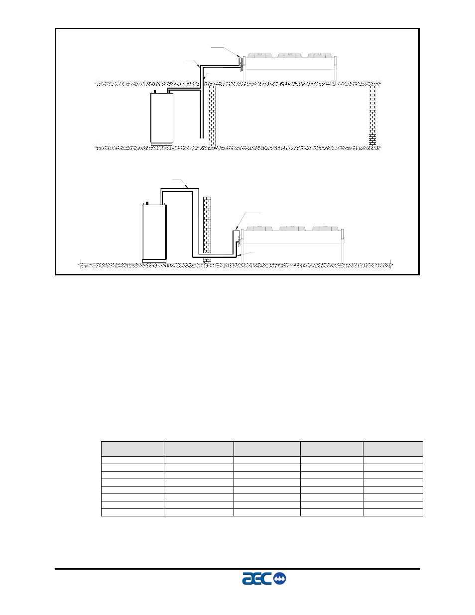
Figure 8
Figure 9
(Figures 8 & 9 – Remote Condenser Piping Trap Locations)
Sizing Refrigerant Lines
To determine field installed liquid and discharge line sizes, it is
first necessary to establish the equivalent length of pipe for each
line, valves, and elbows. Chiller capacity and leaving water
temperature range is also required. Figure 10 states the equivalent
length in feet, for refrigerant valves and fittings.
Example: If the actual length of horizontal piping for an FSSR-5 is
60 feet, the vertical piping is 35 feet, and (4) elbows (Figure 10)
are 6.4 feet. 60 + 35 + 6.4 = 101.4 equivalent feet, therefore the
liquid line piping size (Figure 24) would be 5/8”.
Figure 10
Refrigerant Line Sizing
Line Size
Inches OD
Globe Valve
Equivalent Ft
Angle Valve
Equivalent Ft
Short Radius Elbow
Equivalent Ft
Long Radius Elbow
Equivalent Ft
1/2”
43
15
1.4
0.9
5/8”
55
18
1.6
1.0
7/8”
69
24
2.0
1.4
1 1/8”
87
29
2.7
1.9
1 3/8”
102
33
3.2
2.2
1 5/8’
115
34
3.8
2.6
2 1/8”
141
39
5.2
3.4
2 5/8”
159
44
6.5
4.2
INVERTED TRAP
TRAP
LIQUID LINE
DISCHARGE LINE
INVERTED TRAP
LIQUID LINE
DISCHARGE LINE