4 display, 5 temporary increase and decrease of the output, Fig. 86) – ARAG GCS 3200 User Manual
Page 36
36
USE
15.4
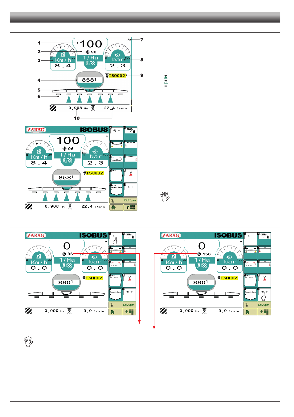
Display
Fig. 85
1 Detected output
2 Set flowrate
3 Speed
4 Tank level (text and graphic)
5 General status
6 Section status:
section ON and Main ON
Section ON and Main OFF
Section OFF
7 Automatic
A
or manual
M
operation
8 Pressure
9 Nozzle being used
10 Customizable data
Fig. 86
A
*
Decreases temporarily the output (par 15.5)
B
*
Gains access to the management of H2O sections and the main command
(par 15.6)
C
*
Gains access to the management of the hydraulic functions (par 15.7)
D
Selects a job already set (par 13.2)
E
Goes back to the previous page of the menu (Fig. 78)
F
Selects the manual or automatic operation mode (par 15.9)
G
Activates the left foam marker (par 15.10)
H
Activates the right foam marker (par 15.10)
I
*
Activates or deactivates the main command (par 15.11)
J
*
Increases temporarily the output (par 15.5)
*
COMMANDS ONLY WORK IF NO AUXILIARY INPUT DEVICE IS
CONNECTED.
15.5
Temporary increase and decrease of the output
Fig. 87
Fig. 88
Press
A
(Fig. 87) to decrease the set output value
96
.
Press
J
(Fig. 88) to increase the set output value
156
.
COMMANDS ONLY WORK IF NO AUXILIARY INPUT DEVICE IS CONNECTED.