Priority marking configuration example, Network requirements, Configuration procedure – H3C Technologies H3C S12500 Series Switches User Manual
Page 71
62
Step Command
Remarks
14.
Apply the QoS policy.
•
Applying the QoS policy to an interface
•
Applying the QoS policy to a VLAN
•
Applying the QoS policy globally
Choose one
application
destination as
needed.
15.
Display the priority marking
configuration.
display traffic behavior user-defined
[ behavior-name ] [ | { begin | exclude | include }
regular-expression ]
Optional.
Available in any
view.
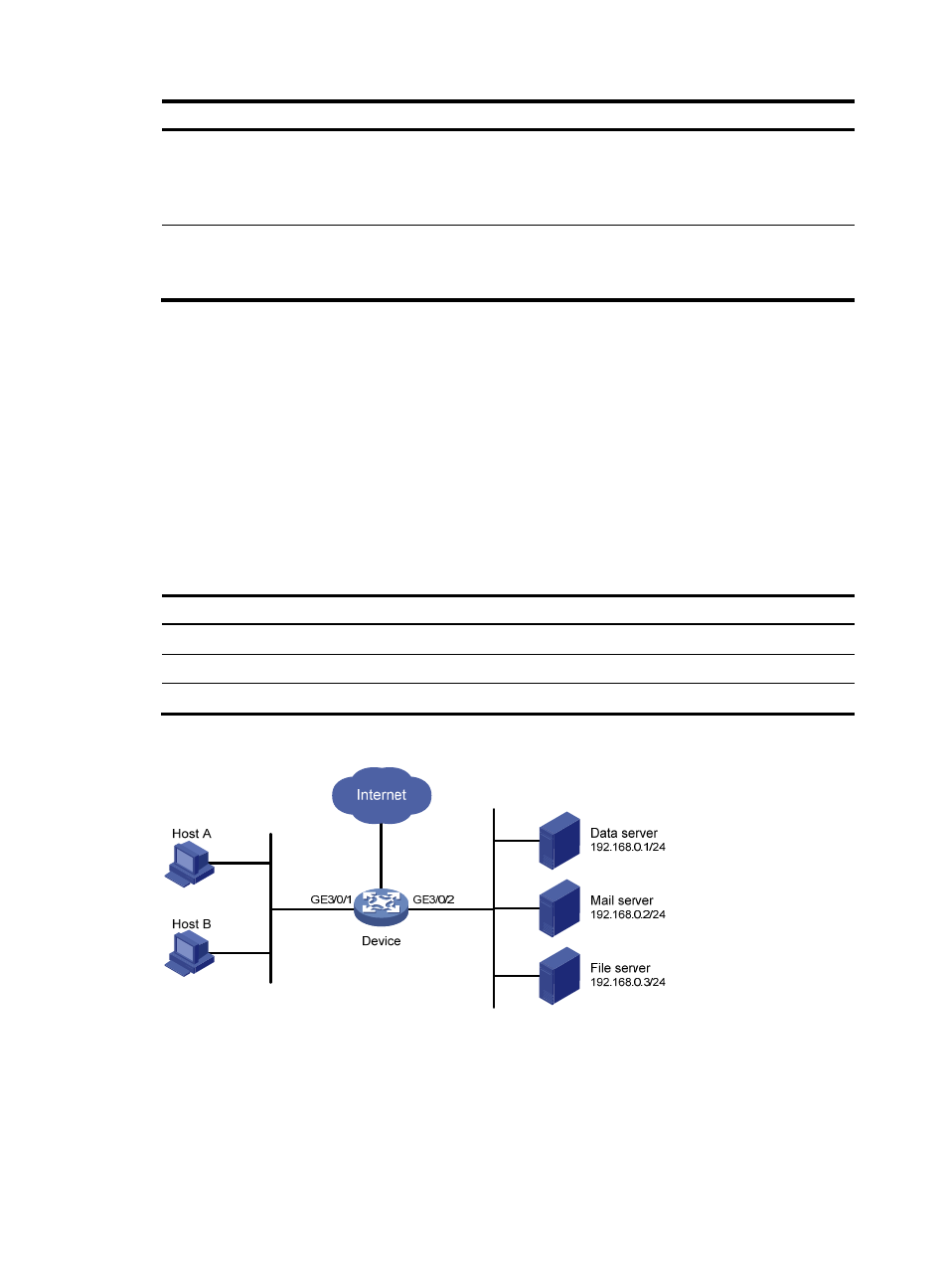
Priority marking configuration example
Network requirements
As shown in
, the enterprise network of a company interconnects hosts with servers through
Device. The network is described as follows:
•
Host A and Host B are connected to GigabitEthernet 3/0/1 of Device.
•
The data server, mail server, and file server are connected to GigabitEthernet 3/0/1 of Device.
Configure priority marking on Device to meet the following requirements:
Traffic source
Destination
Processing priority
Host A, B
Data server
High
Host A, B
Mail server
Medium
Host A, B
File server
Low
Figure 17 Network diagram
Configuration procedure
# Create advanced ACL 3000, and configure a rule to match packets with destination IP address
192.168.0.1.
<Device> system-view