Power supply, Figure 15 – H3C Technologies H3C S9500E Series Switches User Manual
Page 30
20
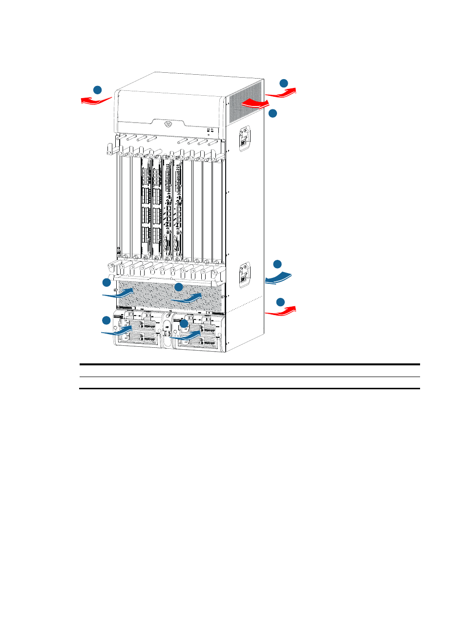
Figure 15 S9508E-V airflow
(1) Chassis air intake
(2) Chassis air outlet
(3) Power supply air intake
(4) Power supply air outlet
If an impedance carrier is installed in an S9508E-V, ambient air only exhausts through the air vents at the
top of the chassis, but does not flow in at the chassis rear. For more information about the impedance
carrier, see "Installing the switch."
Power supply
To meet the power supply requirements:
1.
Calculate the system power consumption.
2.
Select power supplies according to the system power consumption and power supply mode.
To ensure proper operation of the switch, make sure the maximum output power of the power
supplies is greater than the system power consumption of the switch (reserve certain power for
redundancy). After determining the system power consumption and power supply mode (AC or
DC power supply), you can select power supplies as needed.
3.
Verify that the power source on the installation site meets the requirements of the power supplies.
Make sure the power source of the installation site is steady and can meet the input requirements
of the power supplies, including the input method and rated input voltage.
1
1
2
3
3
4
2
2
1