Wfq queuing, Own in, Figure 6-3 – H3C Technologies H3C S7500E Series Switches User Manual
Page 64
6-3
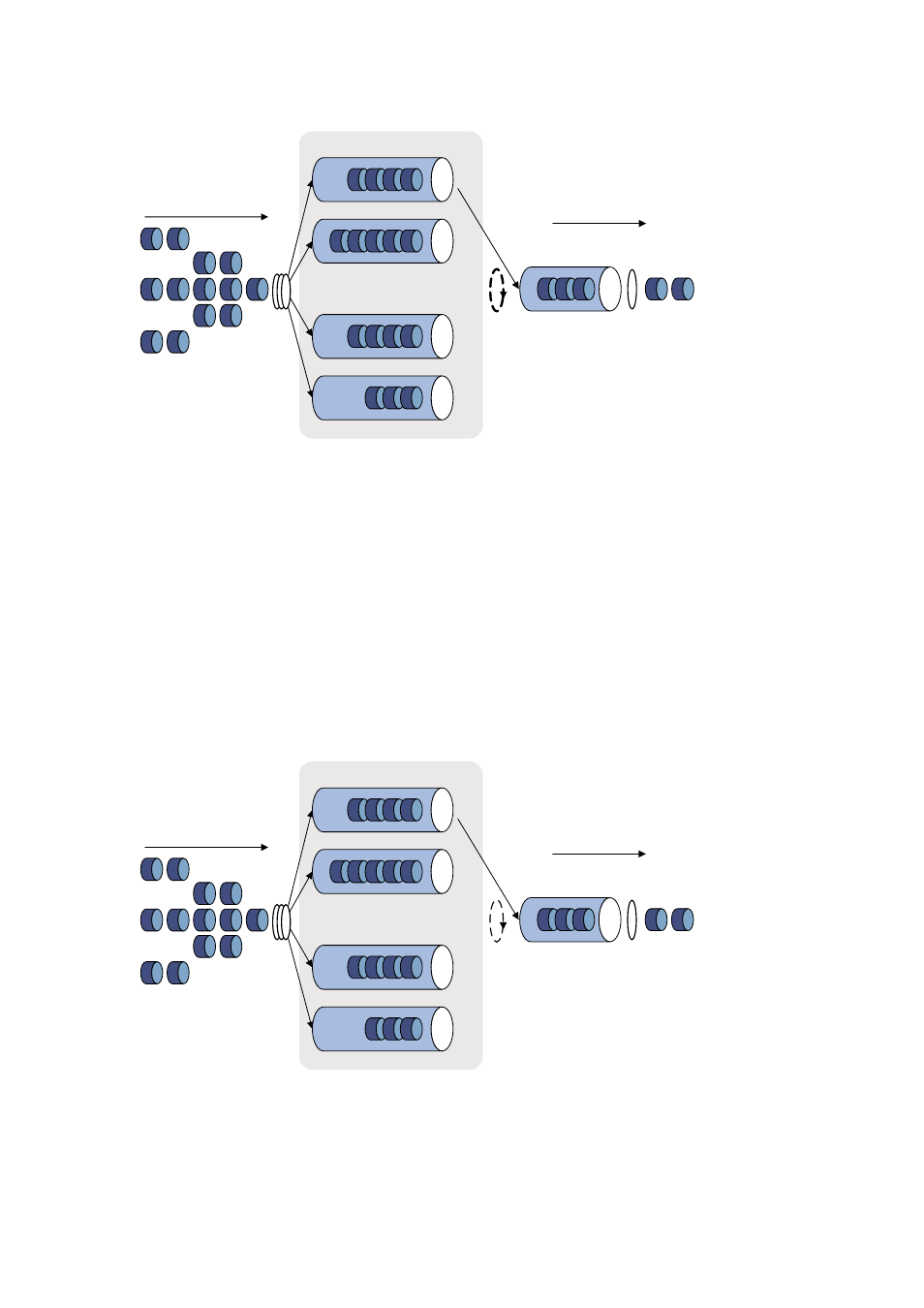
Figure 6-3 Schematic diagram for WRR queuing
Queue 0 Weight 1
……
Queue 1 Weight 2
Queue N-2 Weight N-1
Queue N-1 Weight N
Packets to be sent through
this port
Sent packets
Interface
Queue
scheduling
Sending queue
Packet
classification
Assume there are eight output queues on a port. WRR assigns each queue a weight value
(represented by w7, w6, w5, w4, w3, w2, w1, or w0) to decide the proportion of resources assigned to
the queue. On a 100 Mbps port, you can configure the weight values of WRR queuing to 5, 3, 1, 1, 5, 3,
1, and 1 (corresponding to w7, w6, w5, w4, w3, w2, w1, and w0 respectively). In this way, the queue
with the lowest priority is assured of 5 Mbps of bandwidth at least, thus avoiding the disadvantage of
SP queuing that packets in low-priority queues may fail to be served for a long time.
Another advantage of WRR queuing is that while the queues are scheduled in turn, the service time for
each queue is not fixed, that is, if a queue is empty, the next queue will be scheduled immediately. This
improves bandwidth resource use efficiency.
WFQ queuing
Figure 6-4 Schematic diagram for WFQ queuing
Queue 1 Band width 1
……
Queue 2 Band width 2
Queue N-1 Band width N-1
Queue N Band width N
Packets to be sent through
this port
Packet
classification
Sent packets
Interface
Sending queue
Queue
scheduling
WFQ is derived from fair queuing (FQ), which is designed for fairly sharing network resources,
reducing the delay and jitter of all traffic. FQ fully consider the interests of all queues to ensure that:
z
Different queues have fair dispatching opportunities, preventing a single queue from being
delayed for too long.