Multiplexing stm frames – H3C Technologies H3C SR8800 User Manual
Page 50
43
Multiplexing STM frames
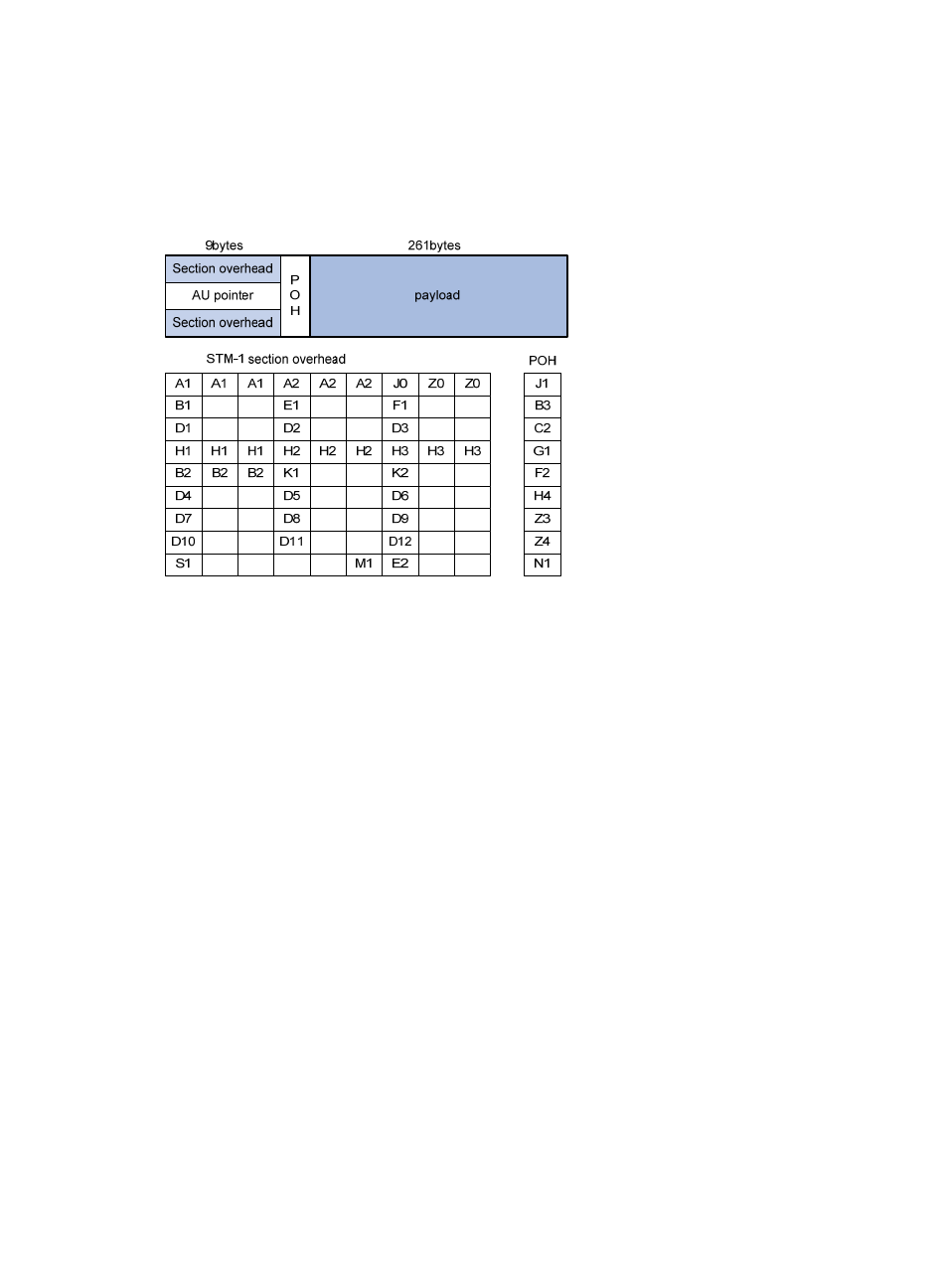
An STM-1 frame adopts the rectangular structure of 270 columns and 9 rows, with the first 10 columns as
the overhead and the rest 260 columns as the payload. An STM-N frame is formed by interleaving N
STM-1 frames.
Figure 14 STM-1 frame structure
•
SOH—The SDH section overhead. It is used for monitoring the entire STM-1 frame and does not
carry user data. The SOH consists of the regenerator section overhead (RSOH) and the multiplex
section overhead (MSOH). For example, B1 and B2 are used for bit error rate test (BERT) for the
frame; A1 and A2 are frame synchronization bytes.
•
AU-PTR—The administration unit pointer. It indicates the location of the payload in the STM-1
frame.
•
POH—Path overhead. It is used for monitoring the payload. For example, the C2 byte in the POH
indicates the payload type, and the G1 byte of the POH indicates whether a bit error is present in
the payload.
•
Payload—If channelization stops, the payload carries user data; if channelization continues, the
payload carries the data of multiplexed lower-order channels.
The following figure shows how four STM-1 frames are multiplexed into an STM-4 frame. In the same way,
four STM-4 frames can be multiplexed into an STM-16 frame.