Calculating e1/t1/e3/t3 channel sequence numbers – H3C Technologies H3C SR8800 User Manual
Page 38
31
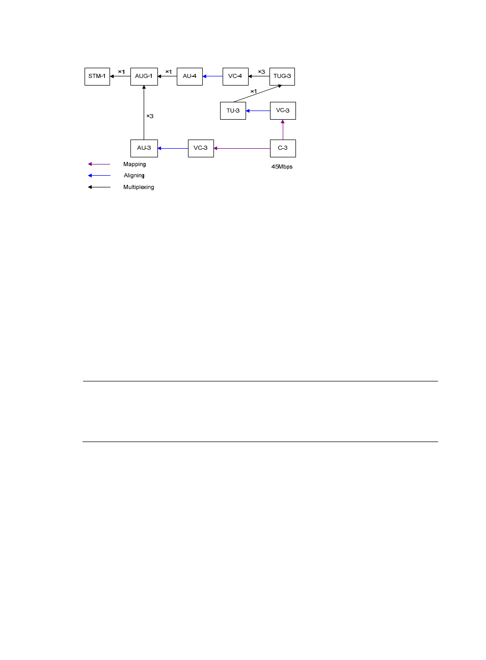
Figure 8 Process of multiplexing T3 channels to form STM-1
In actual applications, different countries and regions may adopt different multiplexing structures. To
ensure interoperability, the multiplex mode command is provided on CPOS interfaces. This allows you to
select the AU-3 or AU-4 multiplexing structure.
Calculating E1/T1/E3/T3 channel sequence numbers
Since CPOS interfaces adopt the byte interleaved multiplexing mode, the lower-order VCs are not
arranged in sequential order in a higher-order VC. To understand how TU numbers are calculated, see
the following example where E1 channels are multiplexed to form STM-1 through the AU-4.
As shown in
, when the AU-4 path is used, the multiplexing structure for 2 Mbps is 3-7-3. The
formula for calculating the TU-12 sequence numbers of different locations in the same VC-4 is as follows:
Sequence number of TU-12 = TUG-3 number + (TUG-2 number – 1) x 3 + (TU-12 Number – 1) x 21
The two TU-12s are adjacent to each other, if they have the same TUG-3 number and TUG-2 number but
different TU-12 numbers with a discrepancy of 1.
NOTE:
The numbers in the aforementioned formula refer to the location numbers in a VC-4 frame. TUG-3 can be
numbered in the range of 1 to 3; TUG-2 in the range of 1 to 7 and TU-12 in the range of 1 to 3. TU-12
numbers indicate the order in which the 63 TU-12s in a VC-4 frame are multiplexed, that is, E1 channel
numbers.