Configuration procedure – H3C Technologies H3C SR8800 User Manual
Page 60
53
•
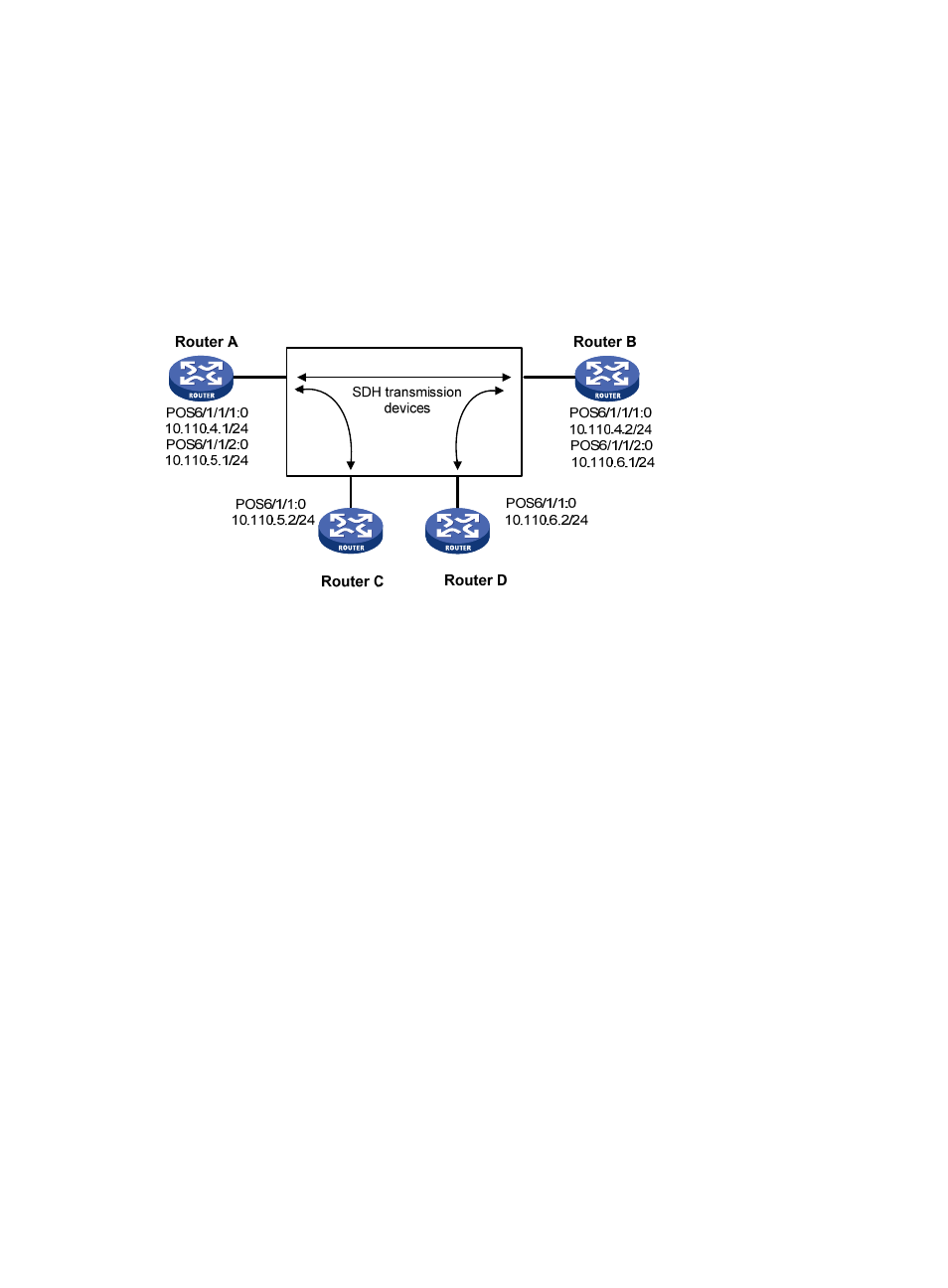
Channelized interface POS 6/1/1/1:0 of Router A is connected to channelized interface POS
6/1/1/1:0 of Router B through an SDH transmission router.
•
Channelized interface POS 6/1/1/2:0 of Router A is connected to interface POS 6/1/1:0 of
Router C through an SDH transmission router.
•
Channelized interface POS 6/1/1/2:0 of Router B is connected to interface POS 6/1/1:0 of
Router D through an SDH transmission router.
•
Each interface uses PPP on the data link layer; all routers use the clock of the SDH transmission
router; the MTU of each interface is 9100 bytes.
Figure 18 Network diagram
Configuration procedure
1.
Configure Router A:
# Configure the clock mode of interface E-CPOS 6/1/1.
<Sysname> system-view
[Sysname] controller E-Cpos 6/1/1
[Sysname-E-Cpos6/1/1] clock master
# Create two 155 Mbps POS interfaces on interface E-CPOS 6/1/1.
[Sysname-E-Cpos6/1/1] using oc-12
[Sysname-E-Cpos6/1/1] oc-3 1
[Sysname-E-Cpos6/1/1-oc-3-1] using oc-3c
[Sysname-E-Cpos6/1/1-oc-3-1] quit
[Sysname-E-Cpos6/1/1] oc-3 2
[Sysname-E-Cpos6/1/1-oc-3-2] using oc-3c
[Sysname-E-Cpos6/1/1-oc-3-2] quit
[Sysname-E-Cpos6/1/1] quit
# Configure channelized interface POS 6/1/1/1:0.
[Sysname] interface Pos6/1/1/1:0
[Sysname-Pos6/1/1/1:0] ip address 10.110.4.1 255.255.255.0
[Sysname-Pos6/1/1/1:0] mtu 9100
[Sysname-Pos6/1/1/1:0] quit
# Configure channelized interface POS 6/1/1/2:0.
[Sysname] interface Pos6/1/1/2:0
[Sysname-Pos6/1/1/2:0] ip address 10.110.5.1 255.255.255.0
[Sysname-Pos6/1/1/2:0] mtu 9100