H3C Technologies H3C MSR 50 User Manual
Page 16
8
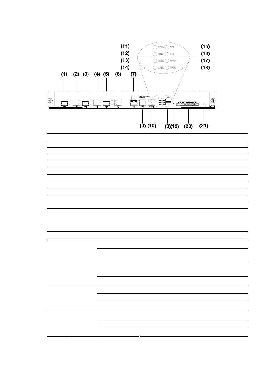
Figure 10 Big view of the LEDs and interfaces on an MPU-G2
(1) Fixed gigabit optical interface 2
(2) Fixed gigabit electrical interface 2
(3) Fixed gigabit optical interface 1
(4) Fixed gigabit electrical interface 1
(5) Fixed gigabit optical interface 0
(6) Fixed gigabit electrical interface 0
(7) Fixed 100 Mbps electrical interface 0
(8) USB interface
(9) Auxiliary port (AUX)
(10) Console port (CONSOLE)
(11) VCPM LED (VCPM)
(12) ESM LED 1 (ESM1)
(13) ESM LED 0 (ESM0)
(14) USB Slave LED (USB0)
(15) System LED (SYS)
(16) Fan LED (FAN)
(17) Power LED 1 (PWR1)
(18) Power LED 0 (PWR0)
(19) CF card LED
(20) CF card
(21) RESET LED
1.
LED attributes
Table 3 LED attributes
LED Color Status
Meaning
Off
No power input, or the main control board has failed.
Green, blinking (0.5
Hz)
The interface card is running as configured.
Green, blinking (4
Hz)
The system is being booted.
SYS
Green &
yellow
Yellow
The system has failed.
Off
Power 1 is not present.
Steady green
Power 1 is present and working normally.
PWR0
Green &
yellow
Yellow
Power 1 has failed.
Off
Power 2 is not present.
Steady green
Power 2 is present and working normally.
PWR1
Green &
yellow
Yellow
Power 2 has failed.