5 connection of the sma power balancer, 1 configuration, Connection of the sma power balancer – SMA WB 5000A-11 Installation User Manual
Page 36: Configuration
Electrical Connection
SMA Solar Technology AG
36
WB5A_6A-IA-IEN114540
Installation Manual
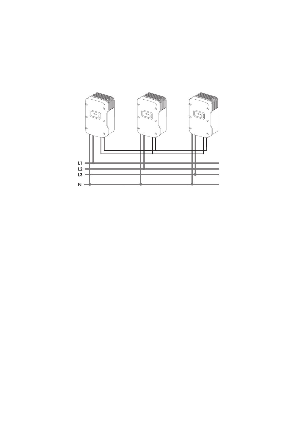
5.5 Connection of the SMA Power Balancer
The inverter is standardly equipped with the SMA Power Balancer. This enables a circuitry of
3 inverters to a three-phase feed-in system.
Each of the three inverters in a group must be connected to a different line conductor of the
low-voltage grid (L1, L2, L3)!
If this electronic circuit is activated, you can specify how the other two inverters should react if there
is a device fault in the third inverter or a line voltage fault occurs in its phase.
The connections for the SMA Power Balancer are galvanically isolated from the rest of the inverter
electronic circuit.
5.5.1 Configuration
With configured country standard VDE-AR-N4105-MP or VDE-AR-N4105-HP, in the WB 5000A-11
and WB 6000A-11, the default setting of the SMA Power Balancer is activated and set to the
operation mode "PowerGuard". With all other country standards, the default setting of the
SMA Power Balancer in WB 5000A-11 und WB 6000A-11 is deactivated.
In WB 5000A/WB 5000A-IT/WB 6000A/WB 6000A-IT, the default setting of the
SMA Power Balancer is always deactivated, regardless of the configured country standard.
The SMA Power Balancer can be activated and configured via a communication product. To change
the "PowerBalancer" parameter, you need a personal access code, the so-called SMA Grid Guard
code. The application form for the personal access code is available in the download area at
www.SMA.de/en, in the "Certificate" category of the respective inverter.
The configuration options are described below.