2 completion of the self-test, Completion of the self-test – SMA WB 5000A-11 Installation User Manual
Page 51
SMA Solar Technology AG
Commissioning
Installation Manual
WB5A_6A-IA-IEN114540
51
6.3.2 Completion of the Self-test
Note the values which are displayed during the self-test. These values must be entered in a test report.
The results of each test test are displayed 3 times, one after the other. The respective message is
displayed for 10 seconds.
In the self-test, the upper and lower disconnection thresholds for each protective function are adjusted
on a linear basis with a variation of 0.05 Hz/s and 0.05 Vn/s for frequency and voltage monitoring.
As soon as the actual measured value goes outside the permitted range
(adjusted disconnection threshold), the inverter disconnects from the power distribution grid.
Thus, the inverter determines the reaction time and performs the self-test.
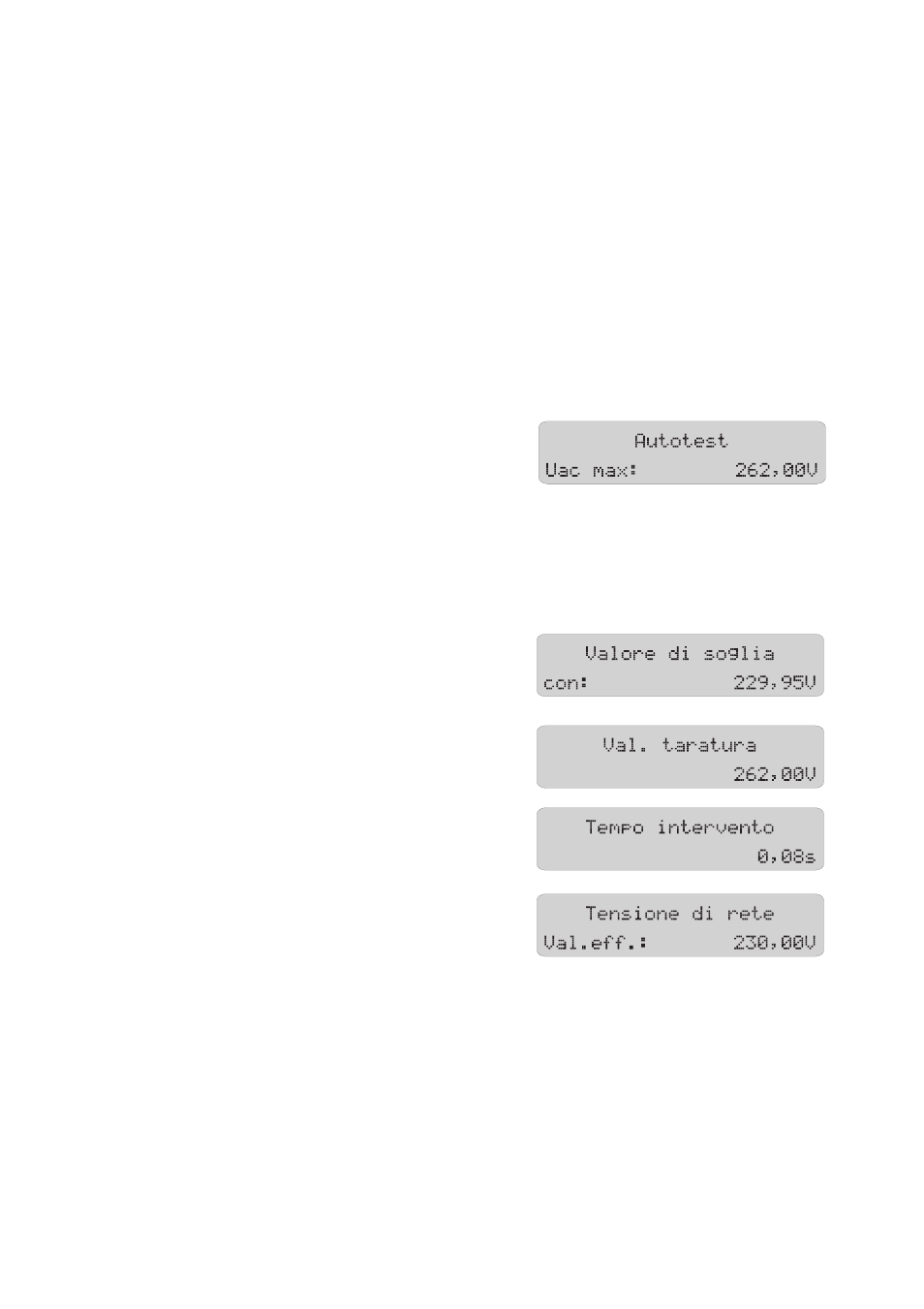
Overvoltage Test
The inverter begins with the overvoltage test. During the
test sequence, the voltage limit applied is shown in the
display of the inverter.
The voltage is reduced step by step until the
disconnection threshold is reached and the inverter
disconnects from the power distribution grid.
Once the inverter has disconnected from the power distribution grid, the display successively shows
the following values:
• Disconnection value,
• Calibration value,
• Reaction time,
• Current line voltage.