MCZ Boxsystem 75 FR User Manual
Page 20
Chapter 4
INSTALLATION AND USE MANUAL
page
20
Installation and assembly
Technical service – MCZ S.p.A. all rights reserved - Reproduction prohibited
component, enlarging the existing ash pit of the firebox or creating it
by drilling the fire bed.
The motor housing has the dimensions: L 270 x H 170 x D 265
You must also provide space for the connection of the two air ducts
with 100 mm diameter, to be connected to the flanges (P) of the motor
housing. Insert the motor housing (M) inside the hole that has been
made in the old fire bed of the firebox.
Now, during this phase, make the air duct connections for the fan by
connecting one end of the flexible piping to the flanges (P) and the
other to the air intakes prepared previously (see next page).
Make a hole as well for the passage of the electrical wiring (N-H) that
connects the control unit (Q) to the motor and the thermostatic probe.
A compartment distant from the hot body of the insert must also
be provided to house the control unit so that it can be accessed for any
maintenance
(see the “Ventilation assembly kit” section).
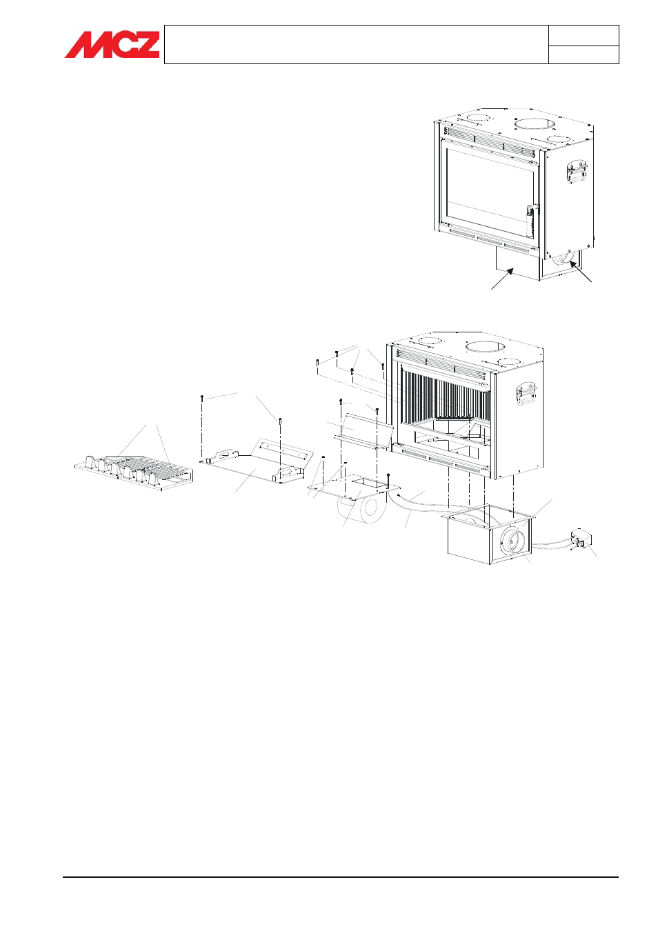
A
B
C
F
G
H
N
M
E
D
L
Q
P
Internal components disassembly/assembly procedures:
1. Extract the cast iron fire beds A
2. Take out the removable bottom C by unscrewing the screws B
3. Remove the deflector E by unscrewing the two screws D
4. Disconnect the probe cable H, unscrew the two nuts F and
extract the motor support G
5. Disconnect the fan motor cable N (mark the position of the
connectors) and
6. Unscrew the screws L that fasten the motor housing and
remove the housing.
7. To reassemble Superclima, repeat the operations in the reverse
order from 6 to 1.
Connect the air ducts as follows:
One of the two outside the home so that it can draw in fresh clean air
and the other inside the room where the insert is being installed. This
procedure allows for proper mixing of the air inside the installation
room and better cooling of the insert structure.
M
P
DIAGRAM 1 - Superclima internal components disassembly and assembly