MCZ Boxsystem 75 FR User Manual
Page 25
Chapter 4
INSTALLATION AND USE MANUAL
page
25
Installation and assembly
Technical service – MCZ S.p.A. all rights reserved - Reproduction prohibited
with the BEAM PROTECTION KIT (optional) or with panels made of
insulating material (Ex: calorite).
To attach the protection, fix the panel to the beam using the
appropriate wood screws provided.
(figure 7)
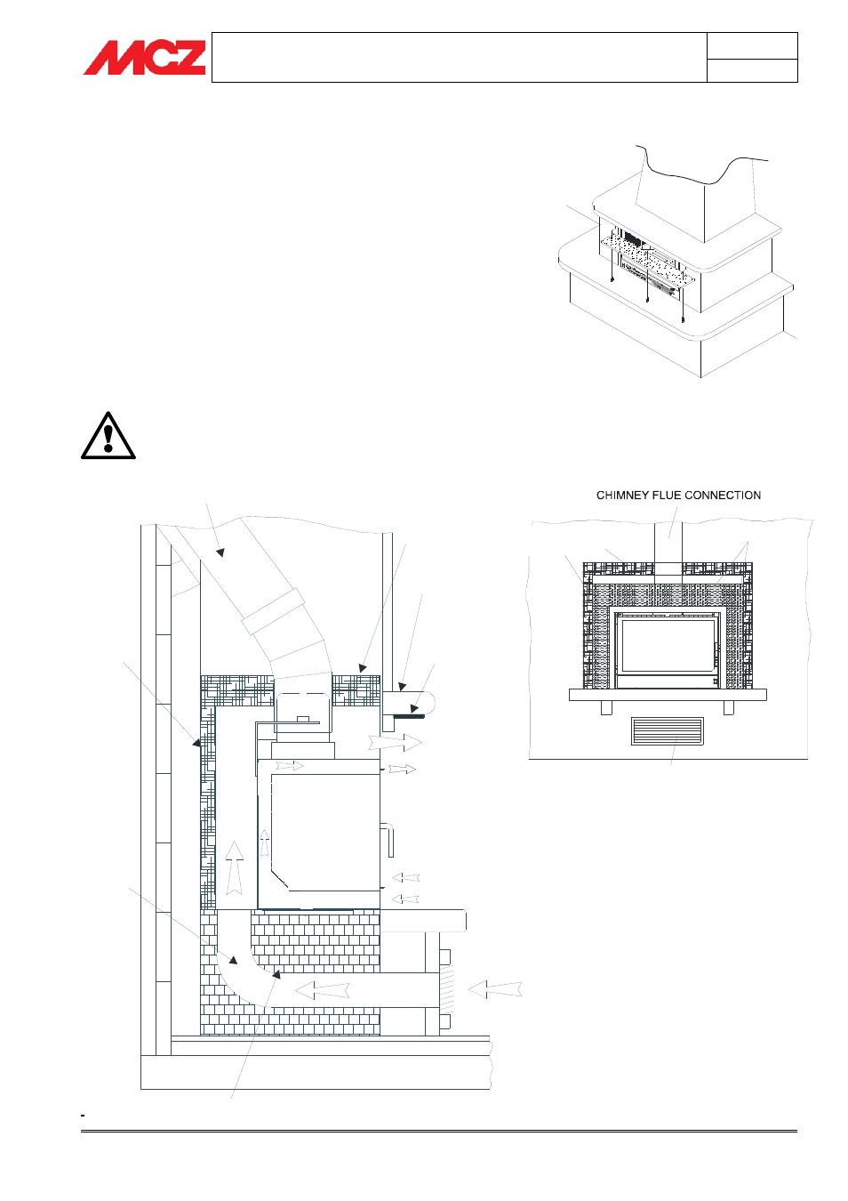
4.13. SUMMARY DIAGRAM FOR IDEAL CONNECTION
OF THE INSERTS
The installation described below is ideal for inserts assembled on old or
new fireplaces; the insert must never be walled up but kept 5mm
detached from any masonry surface since it needs to be able to expand
when it is hot; furthermore, if it is walled up there is a significant drop
(30÷40%) in the thermal efficiency because the heat is not allowed out
completely but only in part.
Insulate the structure thoroughly only if there are
parts in wood or flammable material nearby.
SMOKE CONNECTION
*TOP INSULATION
BEAM
BEAM
INSULATION
CONVECTION
AIR OUTLET
VENTILATION
AIR OUTLET
COMBUSTION AIR INLET
CONVECTION
AIR INLET
SUPPORT IN MASONRY OR SIMILAR MATERIAL
VENTILATION AIR INLET
*R
E
A
R
I
N
S
U
L
A
T
IO
N
C
O
N
V
E
C
T
IO
N
A
IR
D
U
C
T
(U
S
E
F
U
L
F
O
R
T
H
E
E
X
C
H
A
N
G
E
)
Beam protection kit assembly
*Insulation is possible with rigid panels in CALORITE
or similar insulating material.
CONVECTION AIR INLET
COMPENSATION KIT
*
CALORITE
INSULATION