MCZ Boxsystem 75 FR User Manual
Page 24
Chapter 4
INSTALLATION AND USE MANUAL
page
24
Installation and assembly
Technical service – MCZ S.p.A. all rights reserved - Reproduction prohibited
CAUTION !!
• The control unit must be positioned in an accessible
location far from the insert
(see section 4.2.2) to allow any
necessary maintenance or replacement of the internal fuse.
• The equipment must be powered with a voltage of 220 V
at 50 Hz and the power outlet must be accessible and
complete with an earth connection.
• Make sure that the cables do not come into contact with
the hot metal parts of the structure, as they could melt
and short circuit the electrical system.
• The equipment must be connected to a bipolar switch
complete with fuses.
Once the assembly of the ventilation kit is completed,
reassemble the fire bed and the internal components
according to the diagram and description of figure 1 on page
17.
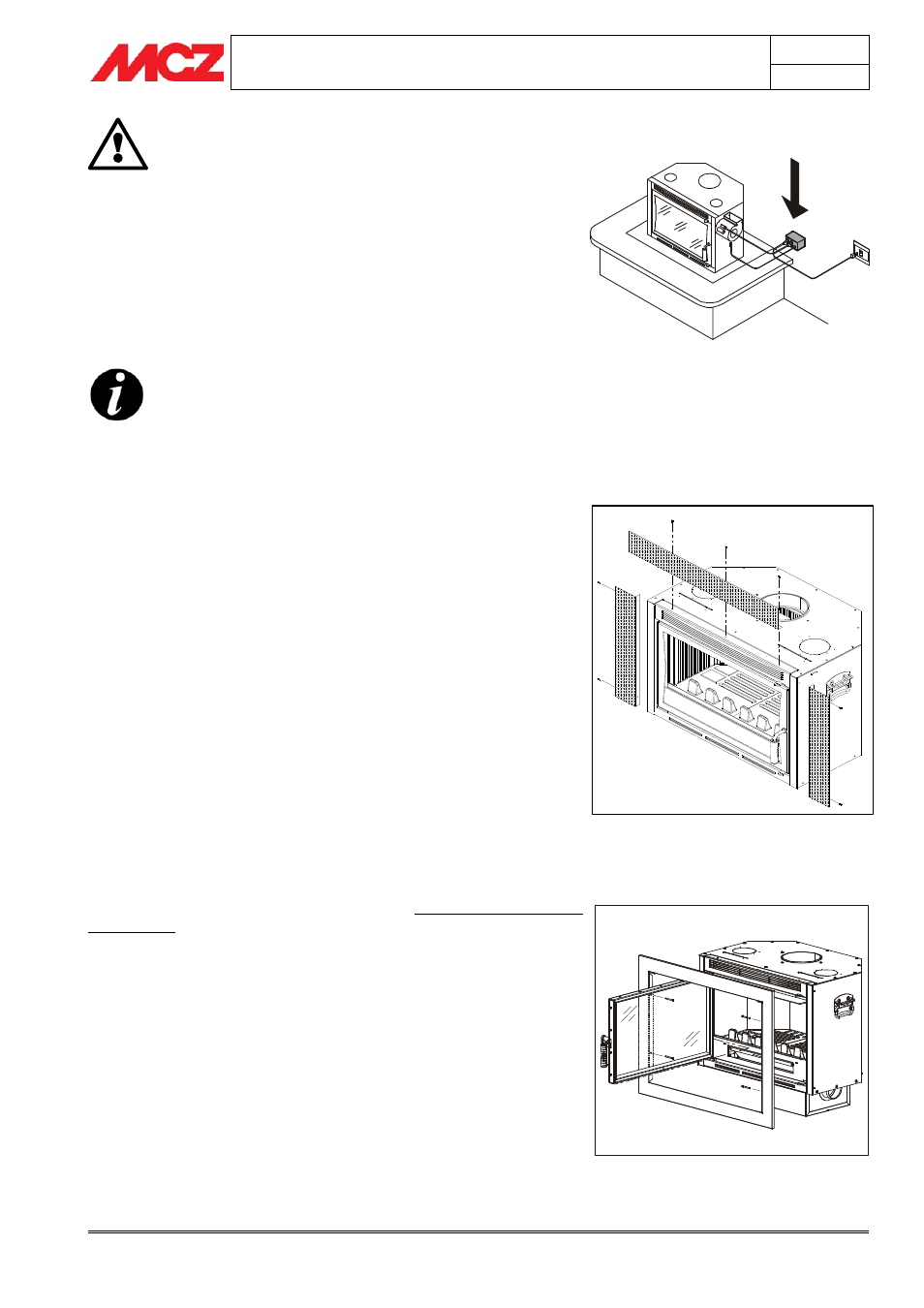
4.10. PERFORATED COMPENSATION FRAME KIT
ASSEMBLY
If there is a space of more than 1 cm between the insert and the
existing firebox, the appropriate compensation frame kit can be
installed which uses a frame in perforated aluminium-clad steel to fill
the cavity between the insert and the firebox.
The MCZ compensation frame has a standard width of 10 cm, while
the length is determined by the perimeter of the product being
installed.
Before inserting the unit, it is necessary to measure the exact
dimensions of the frames, cut them if necessary with sheet metal
scissors if they are too large and fix them with the appropriate self-
tapping screws in the holes already arranged on the outer sides and
roof of the Superclima insert.
Only after the compensation kit has been sized and assembled can the
insert be definitively inserted inside the firebox.
4.11. COMPENSATION FRAME ASSEMBLY
The SmartBox and SuperClima models (not available for the
ClimaSystem) also provide the possibility to assemble an exterior
finishing frame that covers all four sides of the product.
This (optional) frame is assembled only after the installation and
cladding are complete, and it anchors directly to the insert structure.
This frame is designed to finish and cover the crack that is formed
between the metal structure of the unit and the wall.
To assemble the frame, just open the fire door, fit the frame as shown
in the figure and use the four screws provided to fix it onto the stiles of
the structure, inside the profile of the door.
4.12. BEAM PROTECTION KIT ASSEMBLY
If there is a beam made of wood or other combustible material above
the hot air outlet opening, it is absolutely necessary to protect it
Example of control unit positioning
Compensation kit assembly
Compensation frame assembly