MCZ Boxsystem 75 FR User Manual
Page 23
Chapter 4
INSTALLATION AND USE MANUAL
page
23
Installation and assembly
Technical service – MCZ S.p.A. all rights reserved - Reproduction prohibited
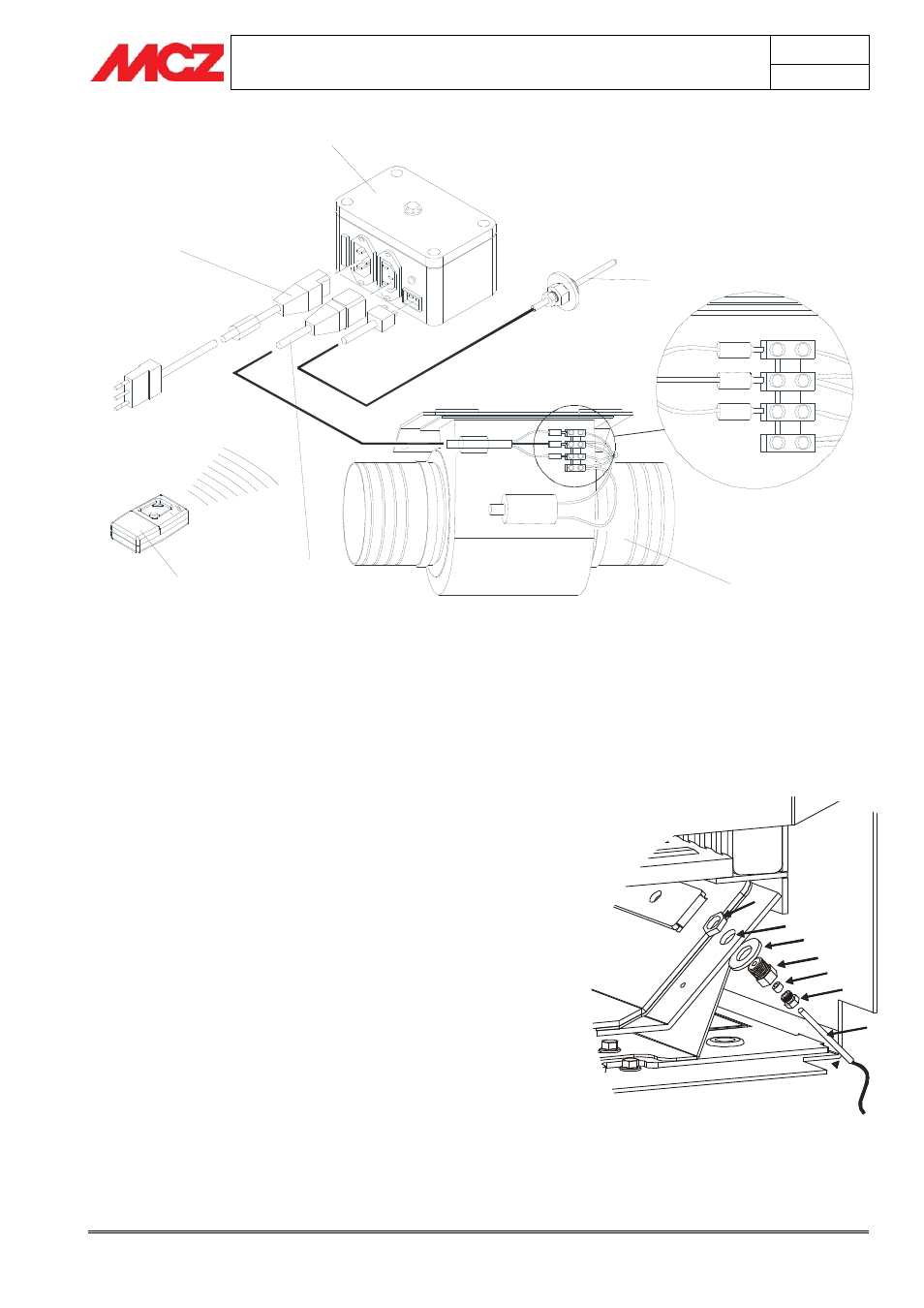
1
2
3
4
5
Yellow-green
Brown
Blue
6
Once all the installation phases have been completed for the connection
to the chimney flue, the compensation kit (if applicable) and the beam
protection kit, it is now possible to definitively insert Superclima inside
the firebox.
The insert, however, has all its internal parts disassembled so it is
necessary to reassemble them properly, beginning with the ventilation
kit
(figure 5), following the steps below:
1. Connect the electrical cable (2) coming from the control unit to
the fan motor, as illustrated in
figure 5
2. Connect the electrical cable of the thermostatic probe (6) to
the cable coming from the control unit
(figure 5)
3. Probe connection for the FC715 control unit
Insert the probe M complete with support screws
(D+F+G+H+L) in the hole E following the procedure below:
(figure 7).
Screw the probe setscrew L onto the probe support G
without tightening, placing the bushing H in between.
Insert the entire probe support G+H+L in the hole E, inserting
the washer F beforehand and blocking the assembly with the
nut D from the side opposite the support.
Insert the probe M in the hole of the probe setscrew L
completely and gently tighten the screw L.
4. Insert the fan motor (5) in the motor housing and connect the
air ducts to the flanges.
5. Connect the control unit (4), located externally as specified in
section 4.2.2, to the home power distribution network and make
sure that the red LED located on the control unit turns on.
Forced ventilation kit
Probe assembly for the FC715 control unit
E
F
G
H
D
M
L