Using the pfl ip core – Altera Parallel Flash Loader IP User Manual
Page 23
period. You must periodically reset this timer by asserting the
pfl_reset_watchdog
pin before the
watchdog time-out period. If the timer does not reset before the watchdog time-out period, the PFL IP
core detects watchdog time-out error and initiates a reconfiguration to load the factory image.
Instantiate the watchdog timer reset circuitry in the configuration image loaded into the FPGA. Connect
one output signal from the reset circuitry to the
pfl_reset_watchdog
pin of the PFL in the CPLD to
periodically send a reset signal to the user watchdog timer. To reset the watchdog timer correctly, hold the
pfl_reset_watchdog
pin high or low for at least two
pfl_clk
cycles.
Note: The user watchdog timer feature for remote system upgrade is available in the PFL IP core in the
Quartus II software version 10.0 onwards.
Using the PFL IP Core
This section describes the procedures on how to use the PFL IP core.
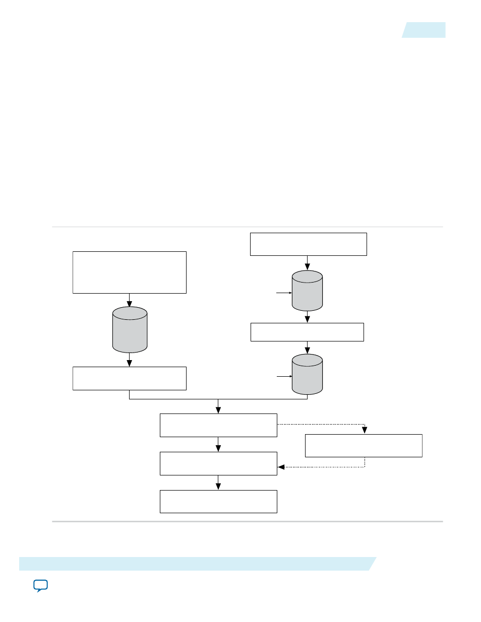
Figure 20: Process for Using the PFL IP Core
Figure shows the process for using the PFL IP core, using MAX II as an example.
Create a new MAX II design,
instantiate the PFL Megafunction in
the MAX II design, and create
Pin Assignments
Add the MAX II .pof to the
Quartus II Programmer
Add the flash .pof in the
Quartus II Programmer
Program the MAX II and Flash Devices
MAX II configures the FPGA with the
configuration data from the Flash Device
Compile and
obtain the
FPGA
.sof(s)
Convert to
.pof for the
Targeted
Flash
Compile
and obtain
MAX II
.pof
Add the .sof(s) for conversion to .pof
Create new FPGA
designs
Create the optional Jam
programming file
UG-01082
2015.01.23
Using the PFL IP Core
23
Parallel Flash Loader IP Core User Guide
Altera Corporation