Specifications – Altera Parallel Flash Loader IP User Manual
Page 48
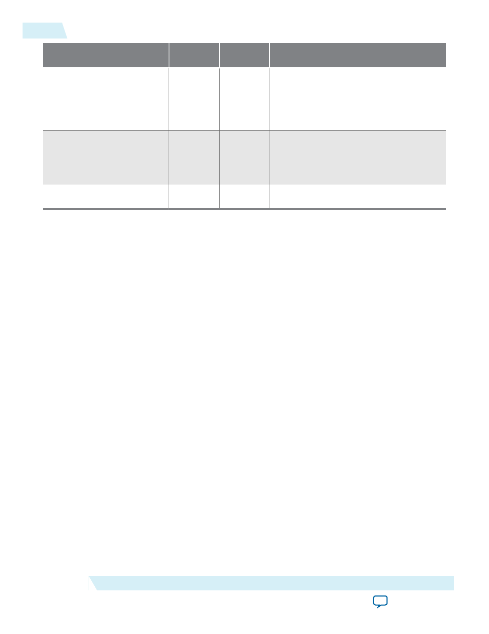
Pin
Description
Weak Pull-
Up
Function
flash_io3[]
Output
—
The fourth bit of the data bus to or from the
quad SPI flash. If you use more than one
quad SPI flash, connect this pin to the fourth
bit of the data bus of all the quad SPI flashes.
The width of this port is equivalent to the
number of quad SPI flashes in the chain.
pfl_reset_watchdog
Input
—
A toggle signal to reset the watchdog timer
before the watchdog timer times out. Hold
the signal high or low for at least two clock
cycles of the
pfl_clk
frequency to correctly
reset the watchdog timer.
pfl_watchdog_error
Output
—
A high signal indicates an error to the
watchdog timer.
Related Information
Provides more information about pull-up configuring pins for specific Altera FPGA families
Specifications
This section provides the equations to estimate the time for reconfiguring the FPGA with the PFL IP core.
The equations in the following table assume the following definitions:
• C
flash
is the number of clock cycles required to read from flash memory.
• C
cfg
is the number of input clock cycles to clock out the data (producing between one and 16 DCLK
cycles, depending on the choice of flash data bus width and FPP or PS mode). Only the larger number
between C
flash
and Ccfg is important because reading from the flash and clocking out the data for
configuration are performed in parallel.
• F
clk
is the input clock frequency to the PFL IP core.
• T
access
is the flash access time.
• C
access
is the number of clock cycles required before the data from the flash is ready.
• T
page_access
is the page read time for Spansion flash memory devices and is only applicable for page
mode access. T
page_access
is set to 30 ns in the PFL IP core.
• N is the number of bytes to be clocked out. This value is obtained from the
.rbf
for the specific FPGA.
48
Specifications
UG-01082
2015.01.23
Altera Corporation
Parallel Flash Loader IP Core User Guide