Icc standby, Clock network information, Standby – Altera PowerPlay Early Power Estimator User Manual
Page 18
3–2
UG-FPGAPWRCAL-2.0
Altera Corporation
PowerPlay Early Power Estimator User Guide: Stratix, Stratix GX & Cyclone FPGAs
October 2005
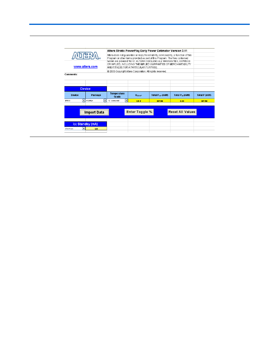
PowerPlay Early Power Estimator Input Values
Figure 3–1. Stratix PowerPlay Early Power Estimator Device & I
CC
Standby Section
I
CC
Standby
I
CC
standby is the current consumed by the device after it is configured,
with no signals driving it and no interconnects toggling. The I
CC
Standby
section of the PowerPlay early power estimator has both a typical and
worst-case value for each device (see
). The typical value is for
a typical process at 25º C. The worst-case value is for a fast process at
85º C.
1
Do not use the worst-case value as a maximum specification,
only as a guideline. Your device’s actual I
CC
standby may vary
from what the PowerPlay early power estimator reports.
Clock Network Information
Stratix and Stratix GX devices feature three types of clock networks:
global, regional, and fast regional. The Clock Network section in the
Stratix and Stratix GX PowerPlay early power estimator is divided into
these three sections:
■
Stratix and Stratix GX devices feature 16 dedicated global clock
networks
■
16 regional clock networks (four per device quadrant)
■
8 dedicated fast regional clock networks (at least two per device
quadrant)