Logic elements, Figure 3–3, Shows the – Altera PowerPlay Early Power Estimator User Manual
Page 21
Altera Corporation
3–5
October 2005
PowerPlay Early Power Estimator User Guide: Stratix, Stratix GX & Cyclone FPGAs
Using PowerPlay Early Power Estimator for Stratix, Stratix GX & Cyclone FPGAs
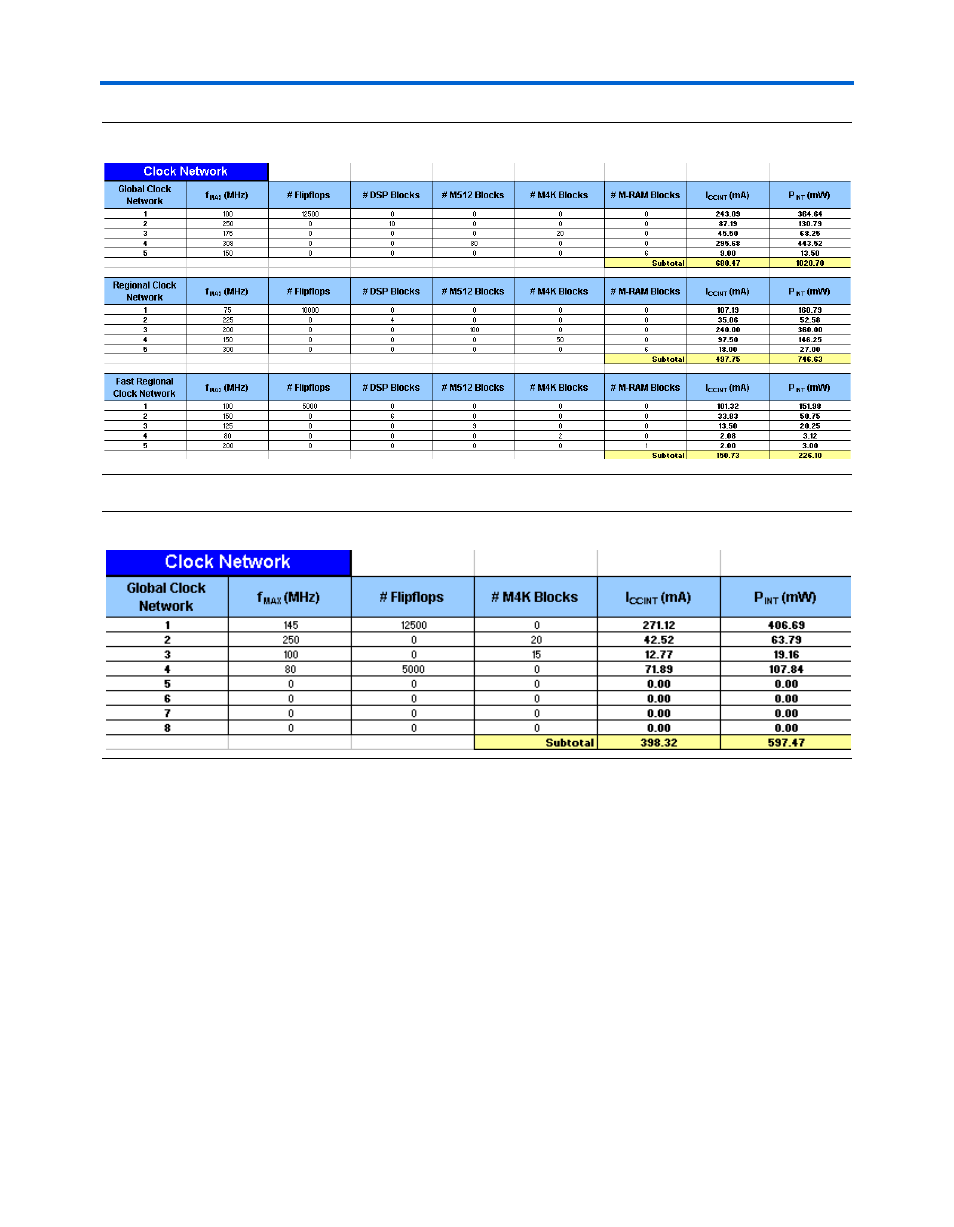
Figure 3–3. Clock Network Section in the Stratix & Stratix GX PowerPlay Early Power Estimator
Figure 3–4. Clock Network Section in the Cyclone PowerPlay Early Power Estimator
Logic Elements
A design can be considered a combination of several design modules
operating at different frequencies and toggle rates. Each design module
can have a different amount of LEs with and without carry-chains. For the
most accurate power estimation, partition the design into different design
modules. You can partition your design by grouping modules by clock
frequency, location, hierarchy, or entities.
Each row in the LEs section represents a separate design module. For each
design module, you need to enter the clock frequency (f
MAX
) in MHz, the
number of LEs fed by this clock, the number of LEs that use carry chains
fed by this clock, and the toggle percentage.