Installation methods, Procedure – CIRCUTOR QNA500 series User Manual
Page 12
POWER QUALITY ANALYZER QNA500 8IO
QNA500 8IO Instruction manual
12 / 111
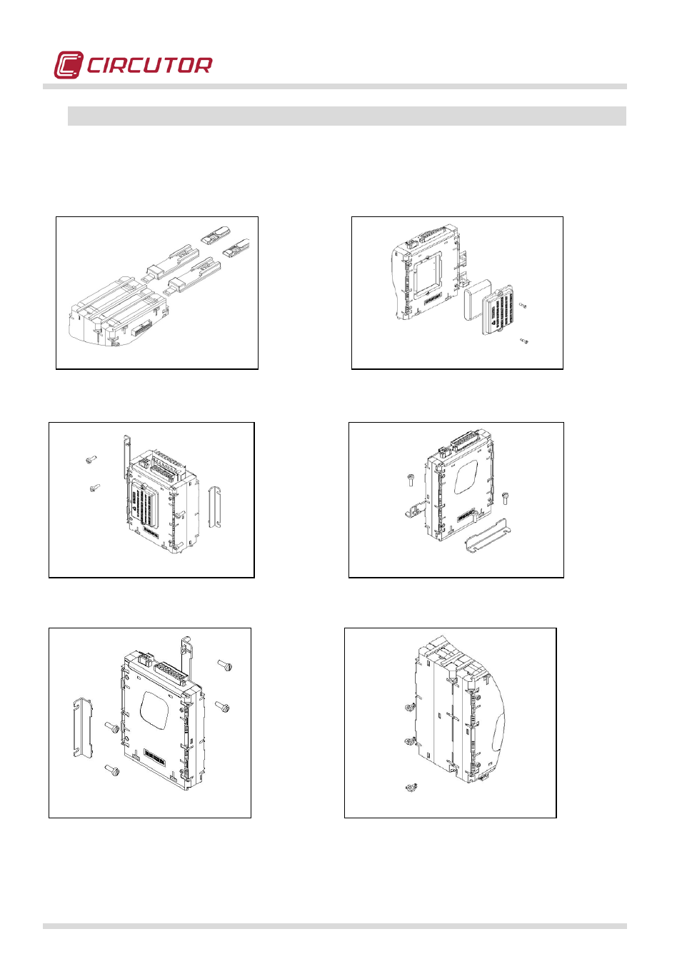
5.3.- INSTALLATION METHODS
The following figures show the different
installation options established when the analyzer is
designed. The equipment's design allows an installation on a rear PANEL or DIN rail.
5.3.1.- PROCEDURE
Illustration 1: Shows how the DIN rail fixing elements should be attached to the rear of the analyzer. Once the guides are in place and the
analyzer has been attached to the DIN rail, remember to raise the guides to make sure they are correctly fastened.
Illustration 2: Shows how the analyzer's battery must be installed on the side of the M-BASE module.
Illustration 3: Shows one of the options for mounting the PANEL base attachment guides. The modules are somewhat symmetrical, and can
therefore be attached to the panel in various ways.
Illustration 4: Shows one of the options for mounting the PANEL base attachment guides.
Illustration 5: Shows how to insert the screws for fastening the analyzer to the PANEL base attachment elements.
Illustration 6: Shows how to insert the plastic clamps to fasten the modules. This point is very important, since the purpose of the clamps is to
guarantee that the modules are firmly secured.
Illustration 3
Illustration 4
Illustration 6
Illustration 5
Illustration 1
Illustration 2