Audio interface to fidelio, Rj45 connector setups – Doremi Fidelio User Manual
Page 30
FDO.OM.001852.DRM
Page 30 of 77
Version 1.5
Doremi Labs
3.3.1.2
Audio Interface to Fidelio
You will now need to connect one BNC cable (NOT provided) to the Fidelio Audio
Interface Box BNC connector label
ed, “AES OUT CH 15/16” (Figure 32).
Connect the other end of this BNC cable to the Fidelio Transmitter box BNC connector
labeled, “AES IN 2” (Figure 33).
Now connect another BNC cable (NOT provided) to the Fidelio Audio Interface Box BNC
connector labe
led, “AES OUT CH 7/8” (Figure 32).
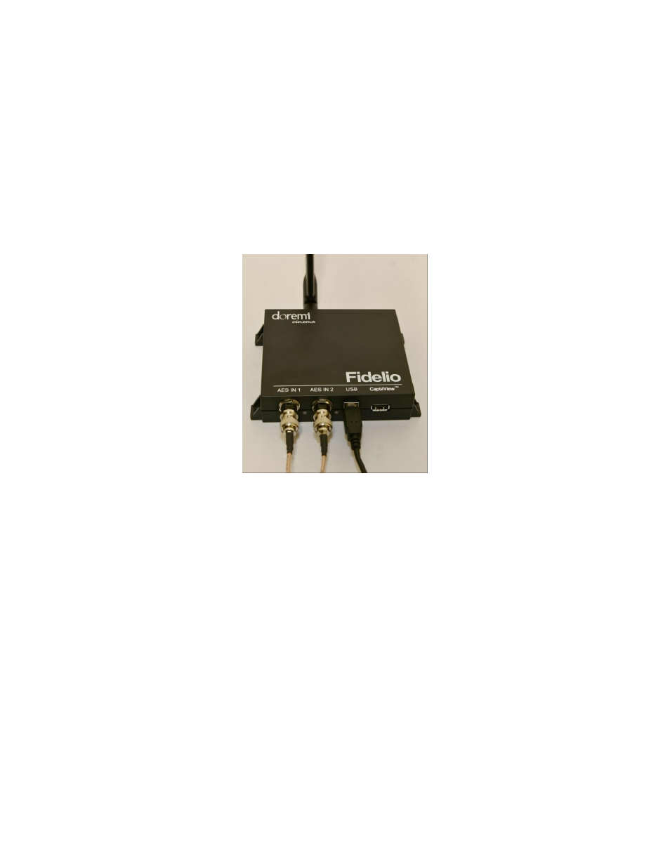
Connect the other end of this BNC cable to the Fidelio Transmitter box BNC connector
labeled, “AES IN 1” (Figure 33).
Figure 33: AES Connection on Fidelio Transmitter
Your connections concerning the projection booth are now complete.
3.3.1.3
RJ45 Connector Setups
If your setup consists of using RJ45 connectors, you will need to disconnect the RJ45
cables from your Doremi Integrated Media Block (IMB).
Then connect these cables to the connectors on the Fidelio Audio Interface Box labeled,
“AES THRU CH 1-6,” and the other cable to the connector that reads, “AES THRU CH
9-
14” (Figure 34).
The other ends on these cables are to remain connected to your audio processor,
respectively.
Using the short RJ45 cable provided, connect one cable into the CH 1-8 AES OUT on
the Doremi IMB and the other end into the AES IN CH 1-8 connector on the Fidelio
Audio Interface box.
Using the other short RJ45 cable provided, connect one cable into the CH 9-16 AES
OUT on the Doremi IMB and the other end into the AES IN CH 9-16 connector on the
Fidelio Audio Interface box.