Audio interface to fidelio, Figure 34) – Doremi Fidelio User Manual
Page 31
Advertising
FDO.OM.001852.DRM
Page 31 of 77
Version 1.5
Doremi Labs
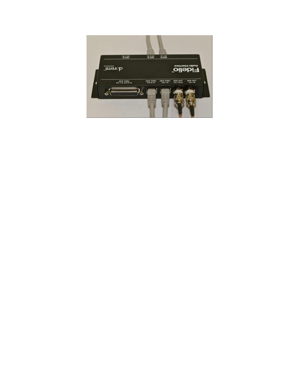
Figure 34: Audio Interface for RJ45 Setups
3.3.1.4
Audio Interface to Fidelio
You will now need to connect one BNC cable (NOT provided) to the Fidelio Audio
Interface Box BNC connector labeled, “AES OUT CH 15/16” (Figure 34).
Connect the other end of this BNC cable to the Fidelio Transmitter box BNC connector
labeled, “AES IN 2” (Figure 33).
Now connect another BNC cable (NOT provided) to the Fidelio Audio Interface Box BNC
connector labeled, “AES OUT CH 7/8” (Figure 34).
Connect the other end of this BNC cable to the Fidelio Transmitter box BNC connector
labeled, “AES IN 1” (Figure 33).
Your connections concerning the projection booth are now complete.
Advertising