Mcs-cc control card, Mcs-ps power supply, Callouts refer to figure 1.7) – Oxmoor MCS User Manual
Page 10: Callouts refer to figure 1.6)
FUSE
POWER
OXMOOR
MADE IN USA BY
OXMOOR CORPORATION
BIRMINGHAM, ALABAMA
®
CHASSIS
MCS-CC
PA-422
IN
PA-422
OUT
1
2
4
8
16
32
64
128
PA-422
ADDRESS
ON
Figure 1.6: MCS-CC Control Card
Figure 1.7: MCS-PS Power Supply Card
MCS-PS POWER SUPPLY
3
3
1
2
1
MCS-PS POWER SUPPLY
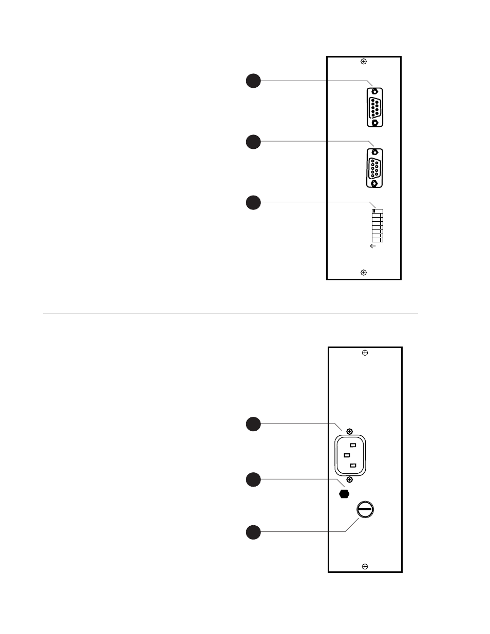
(Callouts refer to Figure 1.7)
One MCS-PS Power Supply card is required for each
MCS Mainframe used. The MCS-PS Power Supply
module provides power for the Mainframe.
1.
POWER CONNECTOR
- Standard IEC 3-pin
connector for AC power cord. Use only with
grounded (3-wire) outlets. Cord sets are available
for all world connection standards.
2.
CHASSIS GROUND POST
- A screw with a star
washer enables the installer to secure a ground
wire to the chassis.
3.
FUSE HOLDER
- Replace only with approved
type of fuse in a rating appropriate to the mains
voltage, as indicated on back panel. (See
SPECIFICATIONS.)
MCS-CC CONTROL CARD
(Callouts refer to Figure 1.6)
One MCS-CC Control Card is required for each MCS
Mainframe used. Communication between a controller
and the MCS-CC Control Card follows PA-422
protocol. The Control Card provides loop-through
connections for PA-422 devices and PA-422 address
selection for the MCS system.
1.
PA-422 IN
- Male, 9-pin D-sub connector. This
port is connected to the PA-422 OUT of the MCS-
MCP Master Control Panel, an MCS-IB Interface
Box or other control devices.
2.
PA-422 OUT
- Female, 9-pin D-sub connector. It
is used to carry the PA-422 data to the next PA-
422 device.
3.
PA-422 ADDRESS
- A selector switch that is used
to assign an address to the MCS system. The MCS
Mainframe and the control device have to be
assigned the same address in order for them to
communicate with each other.
MCS-CC CONTROL CARD
2
Page 8