Mcs-li line input card connections, Contractor - fabricated room panel connections, Connections to a custom room panel – Oxmoor MCS User Manual
Page 16: Refer to figure 2.3), Continued from previous page), Figure 2.2
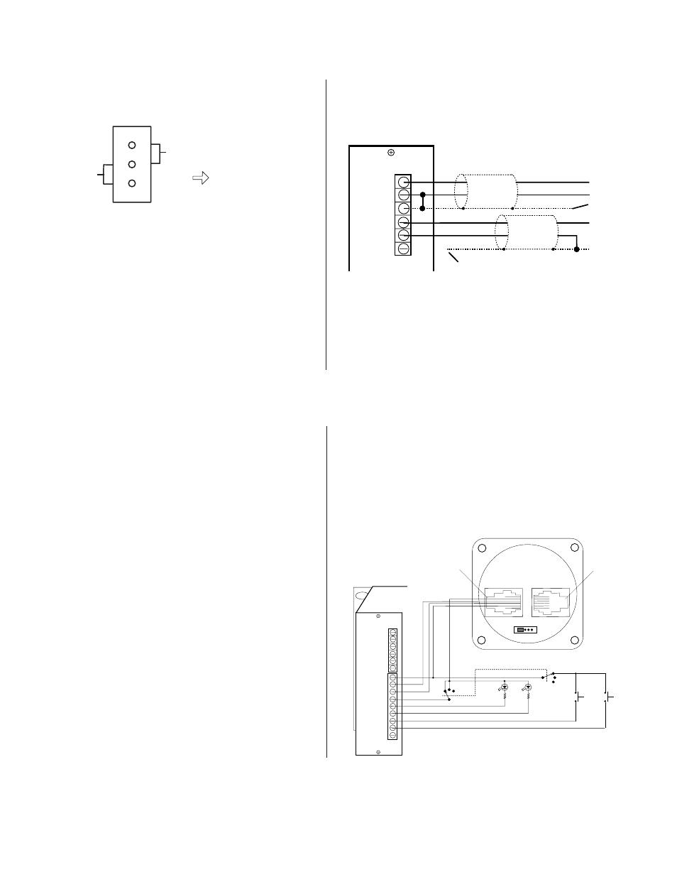
CONNECTIONS TO A CUSTOM ROOM PANEL
(Refer to Figure 2.3)
Figure 2.3 provides the wiring information required to
custom-fabricate a room panel using Oxmoor’s RC-16
Remote Volume Control.
1.
LEDs (D) and Resistors (R)
. High-efficiency LEDs
are recommended for the TALLY indicators. For
an LED that draws 1 mA, an 8 K Ohm current-
limiting resistor should provide suitable
brightness. The value of the resistor will vary
with the current demand of the LED and the
brightness desired. Be certain that the LED/
resistor combination does not exceed the 20 mA,
15 V maximum power provided by the MCS-LI
card.
2.
Security Switch (K1)
. Switch K1 demonstrates
how a 2-pole, 3-throw switch can be wired to
provide the security functions performed by the
key switch on the Oxmoor MCS-RP Room Panel.
If no switchable security functions are desired,
Figure 2.1: Balanced/Unbalanced Jumper
MCS-LI
IN +
IN -
SHIELD
OUT +
OUT -
SHIELD
HIGH
LOW
LOW
HIGH
NC
NC
Figure 2.2:
Figure 2.2:
Figure 2.2:
Figure 2.2:
Figure 2.2: MCS-LI Unbalanced Audio
IMPORTANT NOTE:
The output wiring configuration
shown above is correct ONLY if the Balanced/Unbalanced
Jumper Block has been moved to the unbalanced position.
CONTRACTOR - FABRICATED ROOM PANEL CONNECTIONS
Figure 2.3: MCS-LI Connection for
Contractor-Fabricated Room Panel
The connector is now configured for unbalanced
output and should be connected to an unbalanced
input as shown in Figure 2.2.
c.
Locate the Balanced/Unbalanced Jumper
Block, J2, immediately behind the audio OUT
terminals.
d. Observing the positions shown in Figure 2.1,
remove the jumper and re-install it in the
unbalanced position.
e.
Slide the MCS-LI card back into the
Mainframe and replace the two mounting
screws.
PIN
2 COMMON
3 CD
4 CU
5 DISP
MCS-LI
CU
DISP
IN -
IN +
COM
OUT +
OUT -
COM
COM
CD
LOCAL TALLY
MUSIC TALLY
LOCAL SELECT
MUSIC SELECT
MUTE
IN
OUT
OXMOOR
RC-16
1
5
OXMOOR CORP. BIRMINGHAM, AL
MADE IN USA
1
6
6
1
PIN
2 COMMON
3 CD
4 CU
5 DISP
MUSIC
SELECT
MUSIC
TALLY
LOCAL
TALLY
LOCAL
SELECT
R
R
D
D
S
S
K1
ON
OFF
VOLUME
ONLY
ON
OFF
VOLUME
ONLY
K1
Page 14
wire as indicated by the ON position of K1.
3.
LOCAL SELECT and MUSIC SELECT (S)
. The
LOCAL and MUSIC SELECT switches are SPST,
Normally Open, Momentary Contact.
4.
WIRE
. Using 22 AWG cable, maximum cable
length between the MCS-LI and each room panel
is 600 m (2000 ft).
MCS-LI LINE INPUT CARD CONNECTIONS
MCS-LI LINE INPUT CARD CONNECTIONS
(Continued from previous page)
BALANCED
UNBALANCED
OUTPUT
TERMINAL
BLOCK
J2