Mcs-lc logic card connections, Refer to figure 2.4) – Oxmoor MCS User Manual
Page 17
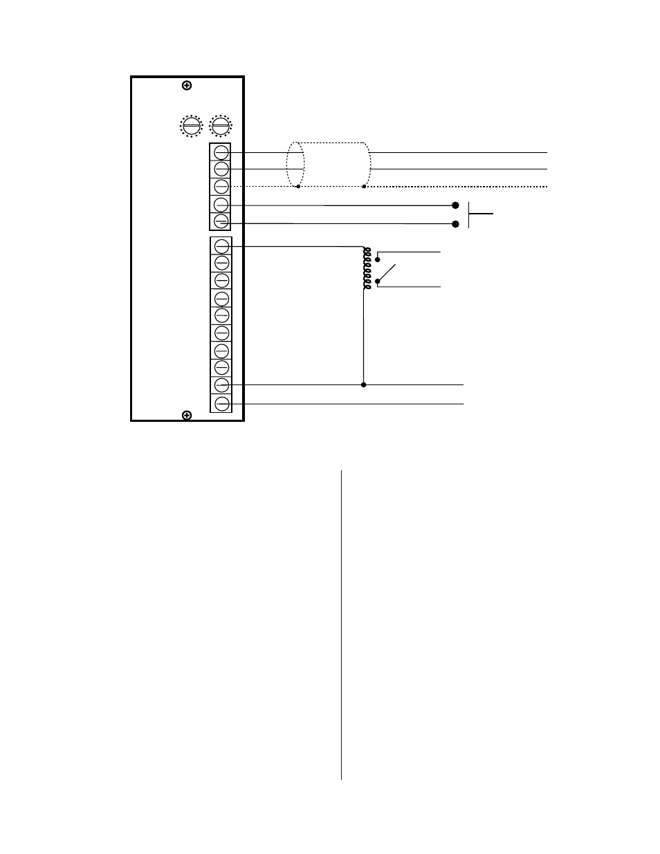
Figure 2.4: MCS-LC Logic Card Connections
MCS-LC
MUSIC IN -
PAGE
MUSIC IN +
COM
SHIELD
COM
COMBINE LEVEL
LOCAL
HEAD 1
HEAD 2
HEAD 3
HEAD 4
HEAD 5
HEAD 6
HEAD 7
HEAD 8
POWER
COM.
MUSIC
+
–
SHIELD
–
+
FROM EXTERNAL
POWER SUPPLY
CONTACT CLOSURE
FOR CHANNEL 1 HEAD
TABLE SPEAKER MUTING
PAGE SWITCH
MCS-LC LOGIC CARD CONNECTIONS
(Refer to Figure 2.4)
1.
MUSIC
. The three MUSIC terminals (MUSIC IN
+, MUSIC IN -, and SHIELD) provide an
electronically balanced input for a background
music source and/or paging. Normal input level
is 0 dBu with maximum input level of + 24 dBu.
The two signal leads connect to MUSIC IN + and
MUSIC IN -; it is good practice to maintain
consistent polarity throughout system wiring. If
the source is unbalanced (single-conductor,
shielded) connect the shield to both the MUSIC
IN - and the SHIELD terminals.
2.
PAGE and COM
. The drawing shows a SPST,
Normally-Open, Momentary-Contact switch wired
between the PAGE and COM terminals. This may
be used to provide paging override. As long as
the circuit is closed, the PAGE logic is pulled low,
causing all MCS-LI Line Input Cards that have
MUSIC SELECT active to default to the
COMBINE LEVEL “MUSIC” volume setting.
When the circuit is again opened, the PAGE logic
is released, allowing all MCS-LIs to return to their
previous volume settings. This PAGE logic is
useful when the MUSIC IN is being used as a
page input to the system.
3.
HEAD 1 through HEAD 8
. Figure 2.4 illustrates
the proper wiring of a HEAD-Table speaker
muting relay and its power supply. HEAD 1
through HEAD 8 provide open-collector outputs
to activate the relays. An output is toggled on or
off by each closure of the corresponding
momentary switch across the HEAD-TABLE
terminals of the MCS-IB Interface Box.
4.
POWER and COM
. POWER and COM connect
to the plus and ground of the relay power supply
to protect the eight open-collector outputs from
the back EMF of the relay coil. Note: It is
important that the POWER and COM terminals
be wired correctly. Do not connect any of the
outputs directly to the plus terminal of the power
supply driving the relays, this may cause damage
to the outputs.
MCS-LC LOGIC CARD CONNECTIONS
Page 15