Mcs-lc logic card – Oxmoor MCS User Manual
Page 9
Page 7
MCS-LC LOGIC CARD
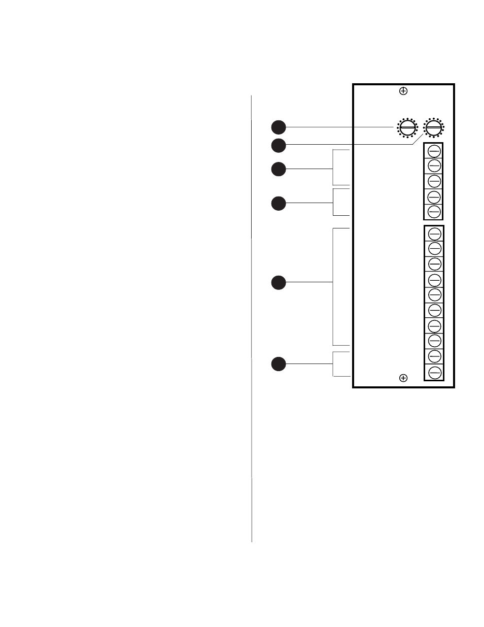
(Callouts refer to Figure 1.5)
One MCS-LC Logic Card is required for each MCS
Mainframe used.
1. LOCAL
- Used to set the COMBINE LEVEL
“LOCAL” default volume setting. When rooms are
combined, or a room is added to a combined
group, all volume controls in the combined group
default to this “LOCAL” volume level.
2. MUSIC
- Used to set the COMBINE LEVEL
“MUSIC” setting. The first time MUSIC SELECT is
activated on one of the MCS-LI cards within a
combined group, all volume controls in the group
default to this “MUSIC” volume level.
3. MUSIC IN
- Designed to be used for background
music and/or paging. Electronically balanced
input, accepts balanced or unbalanced signals from
line-level devices. Normal input level is 0 dBu
with a maximum input level of +24 dBu.
NOT SHOWN:
A screwdriver-adjust level control of this
input is accessible from the front panel.
Every Line Input Card has access to this MUSIC
IN by activating MUSIC SELECT on the desired
MCS-LI Line Input Card.
4. PAGE
- When MUSIC IN is being used as the page
input to the system, the page logic connections
may be used to activate paging overrides.
All MCS-LI Line Input Cards that have MUSIC
SELECT active will default to the COMBINE
LEVEL “MUSIC” volume setting when the PAGE
logic is pulled low. When the page logic is
released all MCS-LIs return to their previous
volume setting.
5. HEAD 1
through HEAD 8 - The HEAD-TABLE
logic provides closures to common for controlling
relays to turn HEAD-TABLE speaker(s) on and off.
The open-collector outputs (HEAD 1 through
HEAD 8) are capable of sinking 0.5 amps to
common. The maximum supply voltage (POWER)
is 50 VDC.
MCS-LC LOGIC CARD
6. POWER
and COM - These should be connected to
the plus and ground of the power supply driving
the HEAD-TABLE relays. This is to protect HEAD
1 through HEAD 8 outputs from any back-EMF
of the relay coil.
NOTE:
Do not connect HEAD 1 through HEAD 8
directly to the plus terminal of the power supply driving
the relays; this will cause damage to the Head-Table
outputs.
1
MCS-LC
MUSIC IN -
PAGE
MUSIC IN +
COM
SHIELD
COM
COMBINE LEVEL
LOCAL
HEAD 1
HEAD 2
HEAD 3
HEAD 4
HEAD 5
HEAD 6
HEAD 7
HEAD 8
POWER
COM.
MUSIC
Figure 1.5: MCS-LC Logic Card
4
6
3
2
5