Mcs-mcp master control panel connections, Refer to figure 2.5) – Oxmoor MCS User Manual
Page 18
Page 16
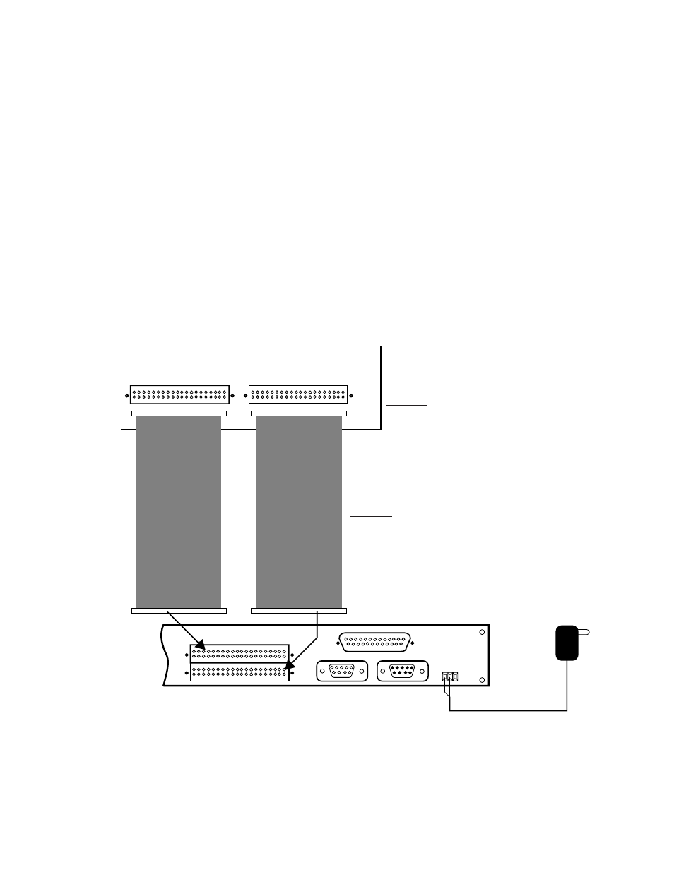
MCS-MCP MASTER CONTROL PANEL
CONNECTIONS
(Refer to Figure 2.5)
The MCS-MCP Master Control Panel and the MCS-IB
communicate with each other by two 40-pin header
connectors. The required data cable will have a
female, 40-pin connector at both ends.
1.
40 Pin Header Connectors
- Interconnect the
MCS-MCP and the MCS-IB.
2.
POWER
- Connect the 12 VDC External Power
Supply (supplied by Oxmoor) to the 12 VDC
connection on the MCS-IB rear panel as
illustrated.
3.
After ALL system interconnections have been
made, plug the MCS-IB External Power Supply
into the equipment rack’s mains supply.
4.
If the Master Control Panel is communicating
with the Mainframe, all tally LEDs will blink
momentarily and then stay on or off depending
upon their control line status.
If the Master Control Panel is NOT
communicating with the Mainframe, all tally
LED’s will continue to flash until communication
is established.
Figure 2.5: MCS-MCP Master Control Panel Connections
MCS-MCP MASTER CONTROL PANEL CONNECTIONS
MCS-IB INTERFACE P1
MCS-IB INTERFACE P2
MCS-MVP INTERFACE
PA-422 OUTPUT
MCS-MCP INTERFACE
PA-422 INPUT
+ 12V DC
COM
COM
P2
P1
2 FORTY-PIN RIBBON
CABLES SUPPLIED BY
OXMOOR
MASTER CONTROL
PANEL
INTERFACE BOX