Mcs-ib interface box screw terminal connections, Mcs-ib screw terminal connections, Refer to figure 2.7) – Oxmoor MCS User Manual
Page 20: Page 18
Page 18
1 T 2 T 3 T 4 T
5 T 6 T 7 T 8 T
1 T 2 T 3 T 4 T 5 T 6 T
7 T 8 T
1 T 2 T 3 T 4 T
5 T 6 T 7 T 8 T
T
T
9 T 10
11
LOCK COM
COM
COM
COM
V+
HEAD TABLE
SOURCE
LINKS
MCS-MVP INTERFACE
PA-422 OUTPUT
MCS-MCP INTERFACE
PA-422 INPUT
+12V DC
OXMOOR
OXMOOR CORPORATION
BIRMINGHAM, ALABAMA
MADE IN USA
SERIAL NUMBER
COM
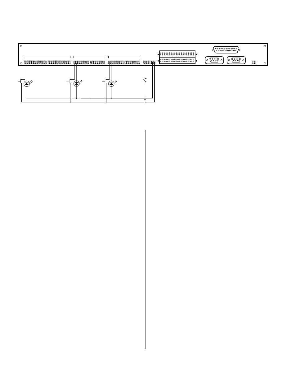
Figure 2.7: MCS-IB Interface Box Screw Terminal Connections
MCS-IB SCREW TERMINAL CONNECTIONS
(Refer to Figure 2.7)
NOTE:
The MCS-IB Interface Box LINK lines must be
programmed (assigned channels to combine) before any of
the audio channels in the MCS system will perform a
combine function. (See page 20 for programming the MCS-
IB LINKS [COMBINE] lines.)
1.
LINKS
. As illustrated in Figure 2.7 above, wire a
momentary contact switch between a numbered
LINK terminal (1 through 11) and the COM
terminal for each LINK line to be programmed.
2.
SOURCE
. Each MCS-LI Line Input Card in the
system has a LOCAL and MUSIC source. These
sources can be turned on and off using the
SOURCE terminals on the Interface Box. Each
SOURCE number corresponds to a Line Input
Card channel in the Mainframe. That is, SOURCE
1 controls the LOCAL and MUSIC sources on
channel 1 of the Mainframe, etc.
As illustrated in Figure 2.7 above, wire a
momentary contact switch between a numbered
SOURCE terminal (1 through 8) and the COM
terminal for each Line Input Card in the system.
NOTE: It is not necessary to wire the SOURCE
terminals if your system does not require muting
the LOCAL and MUSIC sources on the Line
Input Cards. The Interface Box is shipped from
the factory with all SOURCEs un-muted.
3.
HEAD-TABLE
. Each MCS-LI Line Input Card in
the system has a Head-Table logic function
associated with it. The Head-Table logic can be
turned on and off using HEAD-TABLE terminals
1 through 8. Each HEAD-TABLE terminal number
corresponds to a Line Input Card channel in the
Mainframe. That is, HEAD-TABLE terminal
labeled 1 corresponds to MCS-LI card 1 of the
Mainframe.
As illustrated in Figure 2.7 above, wire a
momentary contact switch between a numbered
HEAD-TABLE terminal and the COM terminal
for each Line Input Card in the system.
NOTE: MUSIC SELECT on the associated Line
Input Card overrides the Head-Table function.
The Head-Table function will be active only when
the corresponding Line Input Card is in the
LOCAL source position. When the MUSIC source
is selected, the Head-Table function will be turned
off by the MCS system.
4.
TALLY
. A TALLY connection is provided for
each LINKS, SOURCE and HEAD-TABLE
terminal. The TALLY terminal is labeled “T” and
is located to the right of its controlling terminal.
Connect an LED between the “T” terminal and
V+ for each control line used. A current-limiting
resistor for each LED TALLY is provided in the
Interface Box; an additional resistor is NOT
required. All power required by the TALLY LEDs
is supplied by the Interface Box.
5.
KEY-SWITCH
. Connect a latching key switch
between the LOCK and COM terminals to
provide security against unauthorized system
operation. Maintained contact closure secures
LINKS (COMBINE), SOURCE and HEAD-TABLE
switching functions.
MCS-IB INTERFACE BOX SCREW TERMINAL CONNECTIONS