Mcs programming, Programming the combine buttons, Refer to figure 3.0) – Oxmoor MCS User Manual
Page 22
Page 20
PROGRAMMING THE COMBINE BUTTONS
(Refer to Figure 3.0)
Programming instructs the MCS system as to which
channels are to be combined when a COMBINE button
is pushed.
NOTE:
Your system may have been programmed at the
factory as indicated by a programming sheet attached to
your Master Control Panel or Interface Box.
All programming functions are handled by pressing
and releasing the momentary-contact COMBINE and
SOURCE buttons. In the PROGRAM mode each
SOURCE button becomes a channel-designator button,
used for adding or deleting that channel from the
combination.
Programming requires the following steps:
1.
Remove power from the MCS-IB. Remove the top
panel of the MCS-IB.
2.
If you need to clear all programming to an ALL
unconbined condition follow steps 3 through 5,
otherwise go to step 6.
3.
Move the jumper on JP1 to the two pins away
from the front panel.
4.
Apply power the MCS-IB . One LED on the Master
Control Panel will start blinking.
5.
Remove power from the MCS-IB. Move the
jumper on JP1 to the two pins closes to the front
panel.
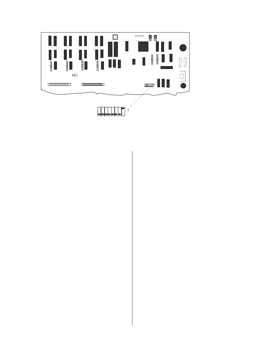
Figure 3.0: MCS-IB or MCS-MCP Micro-Processor Board
MCS PROGRAMMING
NOTE:
PA-422 requires that a
device's address be between 1 and
250. Address 0, 251, 252, 253, 254,
and 256 are illegal.
6.
Apply power the MCS-IB.
7.
Locate SW2 on the microprocessor board. (See
Figure 3.0).
8.
Switch SW2 to the PROGRAM position. The
PROGRAM position is used for programming
only; SW2 must be returned to the RUN position
when programming is completed. (Note: the TEST
position is for factory use only.)
9.
Push the COMBINE button to be programmed.
The corresponding TALLY will illuminate. If this
COMBINE button has been programmed,
SOURCE TALLY indicators will also illuminate to
show which channels are linked by this COMBINE
button.
10.
At this point you may simply add or delete rooms
by push-on/push off operation of the SOURCE
buttons. “On”, TALLY illuminated, indicates the
channel will be added to the combination.
11.
Once you have selected the channels you wish
linked with this COMBINE button, push the
COMBINE button a second time to accept the
program. The LEDs will flash 3 times and then go
out, indicating that programming of this
COMBINE button has been successful.
12.
Repeat steps 9 - 11 above for each of the
COMBINE buttons to be programmed.
13.
Switch SW2 to the RUN position. The system will
not operate with SW2 in the PROGRAM position.
14.
Replace the chassis cover.
Programming is completed.
OXMOOR
OXMOOR CORPORATION
BIRMINGHAM, AL.
MADE IN USA
SW2
SW1
RUN
PROGRAM
TEST
SW3
1
2
4
8
16
32
64
128
ON
1
2
4
8
16
32
64
128
ON
JP1 JP2
FACTORY SET TO
ADDRESS 1