Mcs-ib interface box, Callouts refer to figure 1.11) – Oxmoor MCS User Manual
Page 14
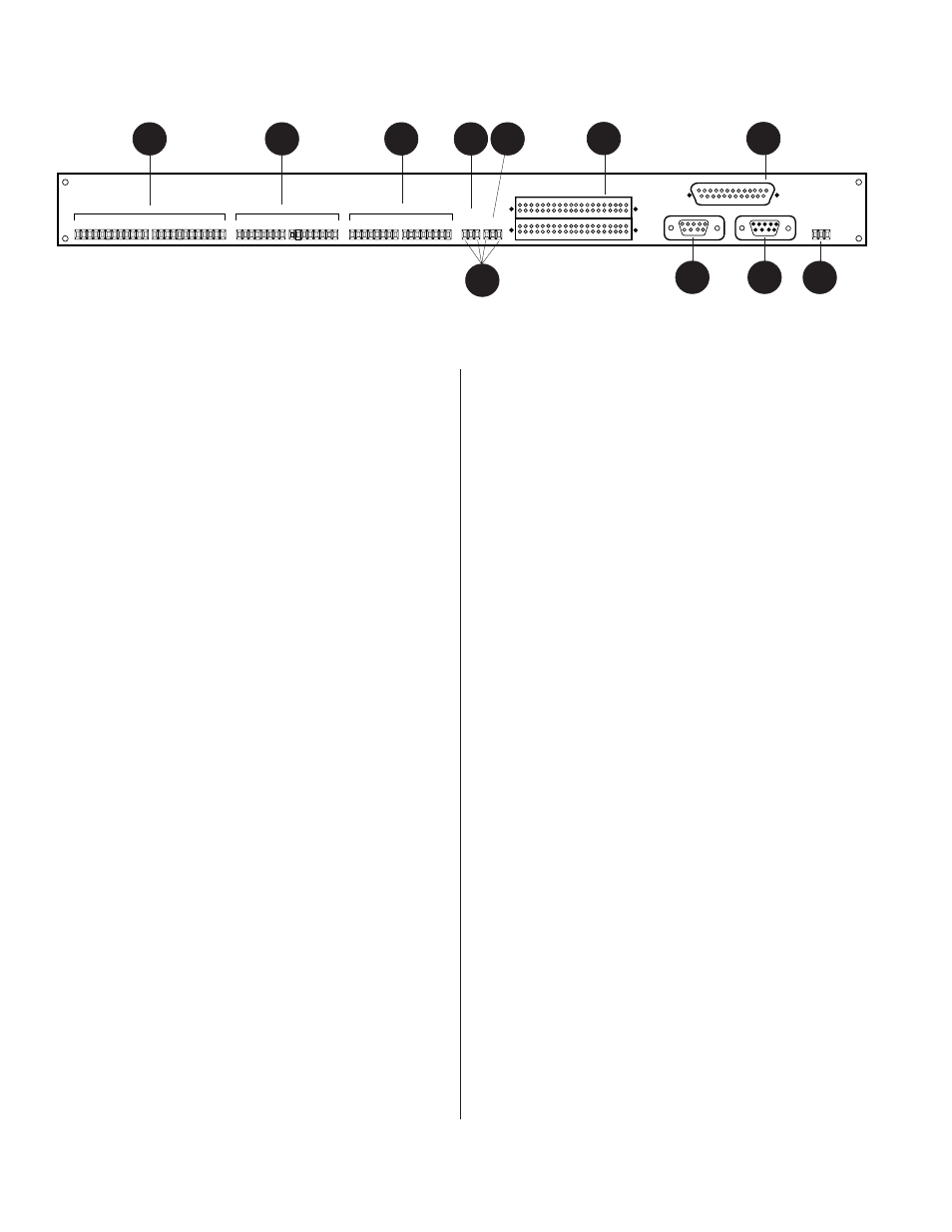
MCS-IB INTERFACE BOX
(Callouts refer to Figure 1.11)
The MCS-IB serves as an interface for:
a.
Contact closures (LINK, SOURCE and HEAD-
TABLE) to PA-422 signals that communicate
with the MCS Mainframe.
b. MCS-MVP Master Volume Panel communi-
cation with the MCS Mainframe.
c.
Programming of the LINKS lines.
1.
LINKS
- Terminal block connections for 11
momentary LINK (COMBINE) switches. Each
LINK line can be programmed to LINK/
COMBINE any combination of the MCS-LI Line
Input modules.
2.
SOURCE
- Terminal block connections for 8
momentary SOURCE switches. The eight
SOURCE terminals correspond to the eight MCS-
LI Line Input modules located in the MCS
Mainframe. Each momentary contact closure
between the SOURCE terminal and COM
“toggles” the associated audio channel’s source
(LOCAL or MUSIC) on or off.
3.
HEAD-TABLE
- Terminal block connections for 8
momentary HEAD-TABLE switches. The eight
HEAD-TABLE terminals correspond to the eight
MCS-LI Line Input modules located in the MCS
mainframe. Each momentary contact closure
between the HEAD-TABLE terminal and COM
“toggles” the associated open-collector output,
HEAD 1 through HEAD 8, (located on the MCS-
LC Logic Card) on or off.
TALLY
- The terminals marked “T”, located to
the right of each LINK, SOURCE and HEAD-
TABLE terminal provide an open-collector closure
to common for a TALLY indicator. The TALLY
1 T 2 T 3 T 4 T
5 T 6 T 7 T 8 T
1 T 2 T 3 T 4 T 5 T 6 T
7 T 8 T
1 T 2 T 3 T 4 T
5 T 6 T 7 T 8 T
T
T
9 T 10
11
LOCK COM
COM
COM
COM
V+
HEAD TABLE
SOURCE
LINKS
MCS-MVP INTERFACE
PA-422 OUTPUT
MCS-MCP INTERFACE
PA-422 INPUT
+12V DC
OXMOOR
OXMOOR CORPORATION
BIRMINGHAM, ALABAMA
MADE IN USA
SERIAL NUMBER
COM
COM
4
7
2
1
3
11
Figure 1.11: MCS-IB Interface Box Rear View
indicator, which may be an LED or an
incandescent (see SPECIFICATIONS), provides
status indication when its associated control line
is active.
4.
LOCK
- Provides security for the LINKS,
SOURCE and HEAD TABLE functions. Designed
for use with a key switch, a maintained contact
closure between LOCK and COM terminals
provides security from unauthorized operation.
5.
V+
- The V+ terminal provides the positive
powering voltage for TALLY indicators.
6.
MCP I/F
- 2 40-pin, male header connectors. Used
to connect the Master Control Panel to the IB box.
7.
MVP I/F
- Standard, 25-pin, female D-sub
connector. Used to connect the MCS-MVP Master
Volume Panel to the MCS system.
8.
COM
- The common terminal for use with
LINKS, SOURCE, HEAD-TABLE, TALLY and
LOCK functions.
9.
PA-422 OUTPUT
- Female, 9-pin D-sub
connector. It is used to handle the exchange of
PA-422 data between the MCS-IB Interface Box
and the Mainframe and/or another PA-422
device.
10. PA-422 INPUT
- Male, 9-pin D-sub connector. It
is used to handle the exchange of PA-422 data
between the MCS-IB Interface Box and the
Mainframe and/or another PA-422 device.
11. 12 VDC
- Provides COM (common) and +
connections for the MCS-IB external powering
module.
MCS-IB INTERFACE BOX
9
10
5
8
6
Page 12