Mcs-mcp master control panel, Operation – Oxmoor MCS User Manual
Page 12
Page 10
SOURCE
HEAD-TABLE
COMBINE
BERKSHIRE ROOM
WYNFREY BALLROOM
SOURCE
HEAD-TABLE
SOURCE
HEAD-TABLE
RIVERCHASE BALLROOM
OFF
ON
COMBINE
COMBINE
3.
Select desired SOURCE or combination of SOURCEs.
Note: Combining rooms will automatically cause the
audio SOURCE in each to default to LOCAL
(typically the local mixer for that room) and to
become “active”. That is, the SOURCEs will mix to
serve the needs of the combined space. The tally LED
will illuminate on each switch to indicate the
SOURCE is active.
To delete a SOURCE from the mix, push the
appropriate SOURCE button. The LED will go off
and the SOURCE will no longer be active. This
should be done with any unused SOURCE, even if
its mixer is off, disconnected or unattended, in order
to eliminate any possibility of undesired additions to
the audio in the combined rooms.
4.
Mute the loudspeaker over the Head-Table
microphone location to reduce the risk of feedback.
Determine the Head-Table location and depress the
HEAD-TABLE switch that corresponds to it. The
tally LED on the HEAD-TABLE switch will
illuminate indicating that speaker muting has
occurred.
5.
Secure system. Once the desired configuration has
been selected, eliminate unauthorized tampering by
turning the key-switch to the OFF position and
removing the key.
1
2
4
3
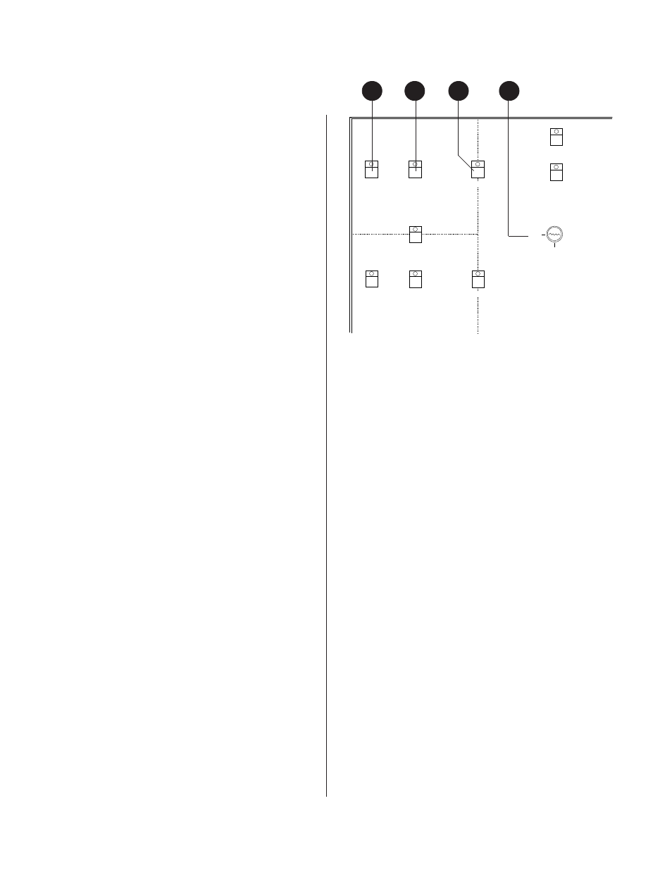
Figure 1.9: Section View of Typical MCS-MCP
MCS-MCP MASTER CONTROL PANEL
(Callouts refer to Figure 1.9)
The MCS-MCP Master Control Panel is typically a
custom control panel that is arranged to depict the
physical layout of the rooms to be combined. The panel
provides a means to combine rooms, select sources, and
activate the Head-Table locations.
1.
HEAD-TABLE
- Momentary push-button switch.
The HEAD-TABLE switch/indicator controls open
collector outputs for driving relays. The relays would
be used to mute the loudspeaker(s) directly over the
location of the Head-Table microphone(s).
2.
SOURCE
- Momentary push-button switch. The
SOURCE switch/indicator mutes/un-mutes the
input of the audio channel dedicated to this room.
This allows the user to determine which rooms will
have active inputs.
3.
COMBINE
- Momentary push-button switch. The
COMBINE switch/indicator combines the audio of
the appropriate rooms and causes the MCS-RP Room
Panels in the combined rooms to synchronize.
4.
KEY-SWITCH
- The Key Switch allows the user to
secure all functions of the MCS-MCP Master Control
Panel.
The switches and tally LEDs shown in Figure 1.9 are
typical of what would be incorporated into a custom
MCS-MCP Master Control Panel from Oxmoor. The
functions of these switches and LEDs may also be
performed by means of another PA-422 control device.
An alternate custom controller, utilizing contact closures,
tally indicators and a locking Key Switch, may be
employed if used with an MCS-IB Interface Box to
translate contact closures to PA-422 signals for
communication with the Mainframe.
OPERATION:
1.
Turn the Key Switch to the ON position. This
enables all Master Control Panel functions until the
switch is returned to the OFF position.
2.
Depress the COMBINE switch which lies on the
intersection of two rooms you wish to combine. The
tally LED on the COMBINE switch will illuminate,
indicating that the two rooms have been combined.
Add any adjacent rooms to the combination as
desired simply by pushing the COMBINE button on
the intersection of another room and any of the
combined rooms.
Note that all of the push-button switches operate in a
“toggling” push on/push off manner.
MCS-MCP MASTER CONTROL PANEL