Neutrino series - quick start guide – Xilica Neutrino Series User Manual
Page 18
Neutrino Series -
Quick Start Guide
XILICA AUDIO DESIGN CANADA / ASIA / EUROPE
Pag
e
18
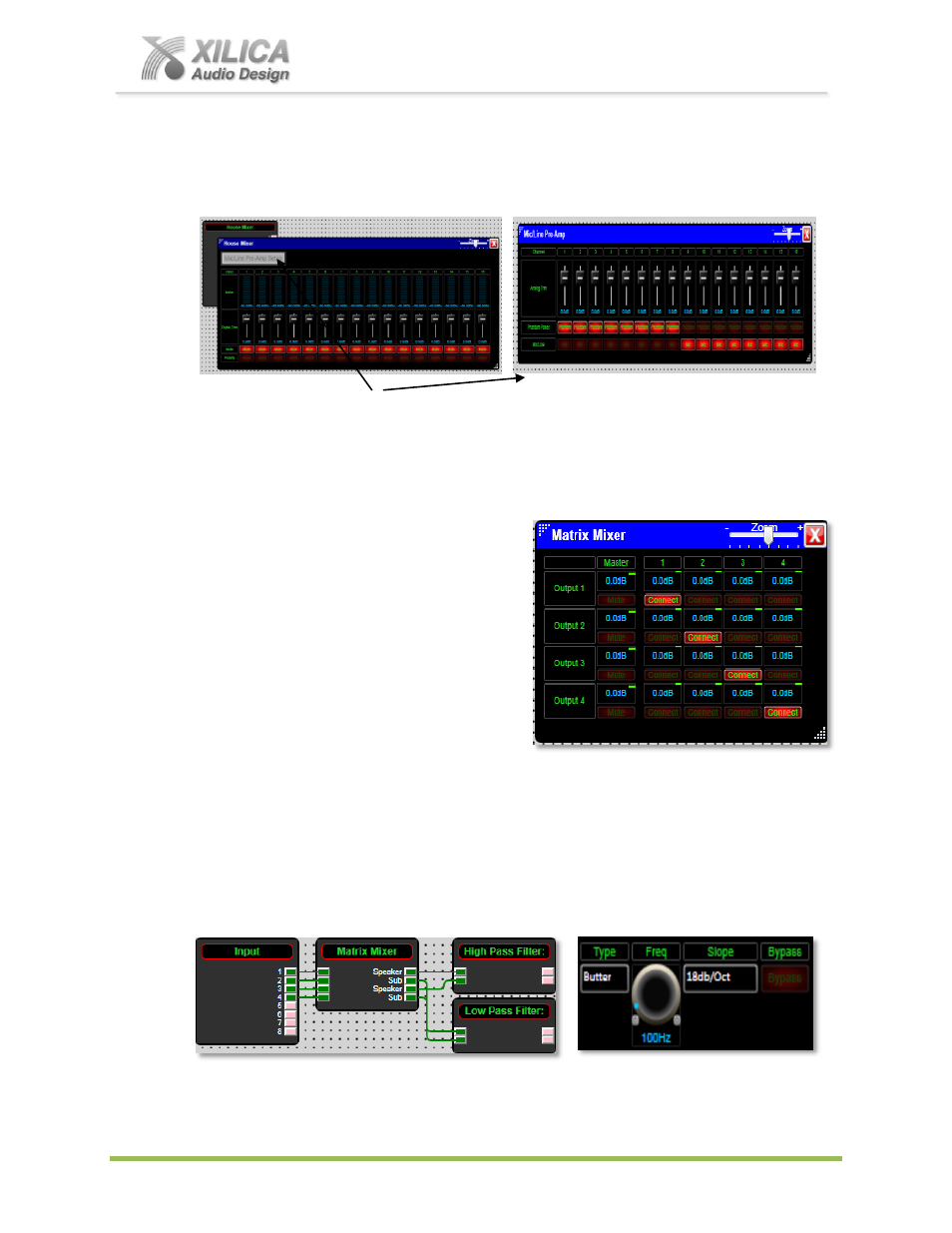
(d) Double clicking on the Analog Input DSP module (re-labeled as House Mixer in our
example) provides access to the Master Input
– Polarity, Mute, Digital Trim, & Meters (below
left) as well as the processors Mic/Line Pre-Amp controls by way of a secondary Grey select
button at the top left of the Input DSP module.
(e) Click the grey
“Mic/Line Pre-Amp Setup” button in the opened Analog Input module (House
Mixer) window above left to display and adjust the processors Mic/Line Pre-Amp parameters
- Mic/Line selection, Phantom Power and Analog Trim (shown above right).
(f) Make appropriate parameter adjustments as required.
(g) Next, double-Click on the Matrix Mixer to
open up the routing matrix. Here input sources
are assigned to any or all outputs. Ensure that
Input 1 routes to Output 1, Input 2 to Output 2
and so on as shown at right. The Connect
button ensures that the signal routes to the
associated output. Turn the Connect Button
OFF when you want to mute the signal going
to the conflicting outputs. The Matrix screen
shot at the right displays the correct routing
assignments for our design example.
For the sake of this example, we are going to designate Outputs 1 and 3 as speaker
channels (high frequencies) and Outputs 2 and 4 as subwoofer channels (low frequencies).
(h) Double click to open the High Pass Filter DSP module. Set the
Type
to Butterworth. The
Slope
to 18 dB/Oct and set the cutoff
Frequency
appropriately.
(i) Open the Low Pass Filter DSP module. Set the
Type
to Butterworth. The
Slope
to 18
dB/Oct and set the cutoff
Frequency
appropriately.
(j) Double-Click the Peak Limiter DSP module to op
en the limiter’s DSP parameters. Ensure
that the threshold is set to 0dB or less.