Assembling and devices coupling, 1 additive modularity linked mode – Analog Way ASCENDER 16 (LIVECORE) - Ref. ASC1602 User Manual User Manual
Page 105
105
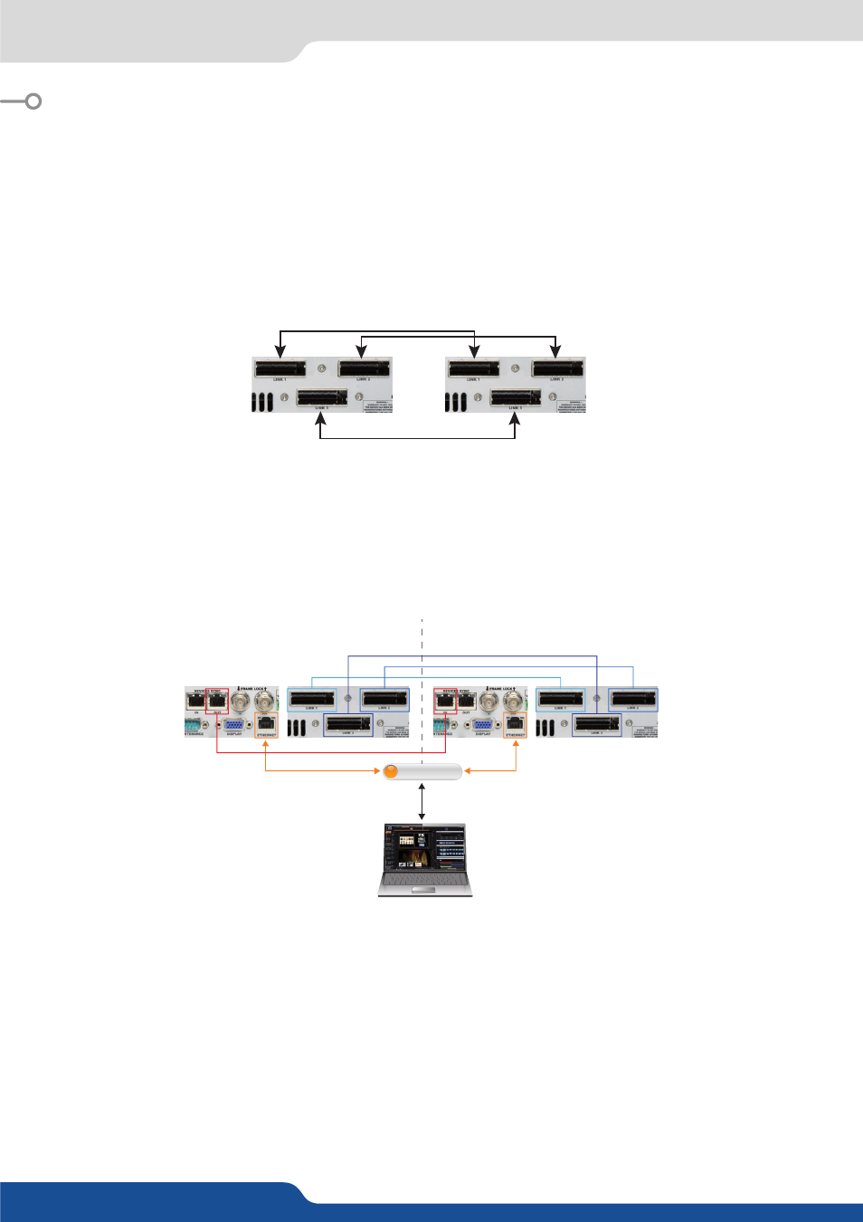
10.1 Additive Modularity Linked mode
10. ASSEMBLING AND DEVICES COUPLING
The LiveCore™ unit can be used in multiple device configuration to share information between device chassis.
This can enable large setups such as a large multi-device screen blend (Hard Edge and Soft Edge).
LiveCore™ units can be linked in two modes:
Additive Modularity Linked mode
allows two units (except NeXtage 16) to share the combined resources
of up to all 24 inputs, 8 outputs, and 2 operator’s monitors using a set of three Livecore Link cables plus a
LAN cable for synchronization. Any input can be routed to any layer on any output, and any combination of
screens can be used, up to 8 outputs blended.
Analog Way cable
Associative Modularity mode
allows for up to four units to be used as part of the same Assembly on the
Vertige™ console. The Device Sync connection assists with synchronization between the various units. In
Associative Modularity configuration, video information must be externally split and shared with all devices
in the Assembly.
10.1 Additive Modularity Linked mode
Once the two devices are wired up, ensure that all devices have unique IP addresses on the network, and
that the gateway IP of all devices is set correctly. If you are not using a router on the network, set all of
the gateway IP addresses to the first or last IP on the network, for example 192.168.2.1 and do not use this
address for any other device.
Lastly, connect to one of the two units, go to the
SETUP >PRECONFIG >LINKED PAGE
, select Linked mode,
and click Refresh to check the connections. If all 5 connection parameters are green, click Start and the units
will synchronize and self-configure for linked operation. If any configuration parameter is red, fix the error
and click Refresh again. All units must be running the same firmware or you will not be able to initiate the
Link mode.
DEVICE MASTER
DEVICE SLAVE
RJ-45
OPT-LINK (x3)
LINK 1
LINK 2
LINK 3
RJ-45
RJ-45
OUT
IN
Web RCS
(Remote Control SoŌware)
On Device Master
ETHERNET HUB