Analog Way ASCENDER 16 (LIVECORE) - Ref. ASC1602 User Manual User Manual
Page 54
54
7.3.10 Input management
Under the SIGNAL tab, you will find:
- ACTIVE PLUG:
Select the plug used by the unit at the moment. Only this plug can be displayed on your
output.
- SETUP PLUG:
Select the plug you want to set up, all changes will be applied to this plug, even if this plug is
active or not.
- SIGNAL TYPE:
Define the type of your signal, video SD/HD YUV/RGB or Computer HV/SOG etc…
- SD STANDARD:
Only available for SD signal, set up to auto (NTSC, PAL, SECAM,…) or manual recognition of
SD signal type.
- SD STABILITY:
Enable or not to define that the signal isn’t stable (VRC type, enlargement of the tolerance)
for stability of SD signal (use stable by default).
- SD COMB FILTER:
Enable or not the comb filter for SD signal. It avoids the interlaced lines problem
- ENABLE:
Enable/disable the input. A disabled input will not appear anymore on the EDIT/LIVE pages and
can’t be assigned to a layer.
- DUAL INPUT:
Status of the input if configured in Dual Link mode.
- LABEL:
Rename your input plug according to your source.
Dual-Link (change only into the Setup Assistant > INPUTS)
The Dual Link DVI and DisplayPort inputs can be supported on the LiveCore™ unit.
You can choose to use the Dual-Link input into the input section under the Setup mode. Select the input #2,
#4, #6, #8, #10 or #12 and select DUAL LINK mode.
Be sure to select the DVI or DisplayPort input plug to see the Dual Link option.
Inputs #2, #6 & #10: DVI
Inputs #4, #8 & #12: DisplayPort
Dual-Head (change only into the Setup Assistant > INPUTS)
The Dual-Head feature is useful when you want to support a high resolution image using more than one cable
as side by side images. In order to use this feature, run your Dual-Head PC board providing you your high
resolution image splitted in 2 cables and plug it into 2 plugs of the LiveCore™ unit.
When the Dual Link feature is active, you will automatically disable the input #1 (linked to input #2), input
#5 (linked to input #6) and input #9 (linked to input #10) as the unit needs those input to handle the dual
link input (in case of DVI). The same thing will happen with inputs #4, #8 & #12 on DisplayPorts. Enabling the
Dual-Link on these inputs disables the inputs #3,#7 or #11.
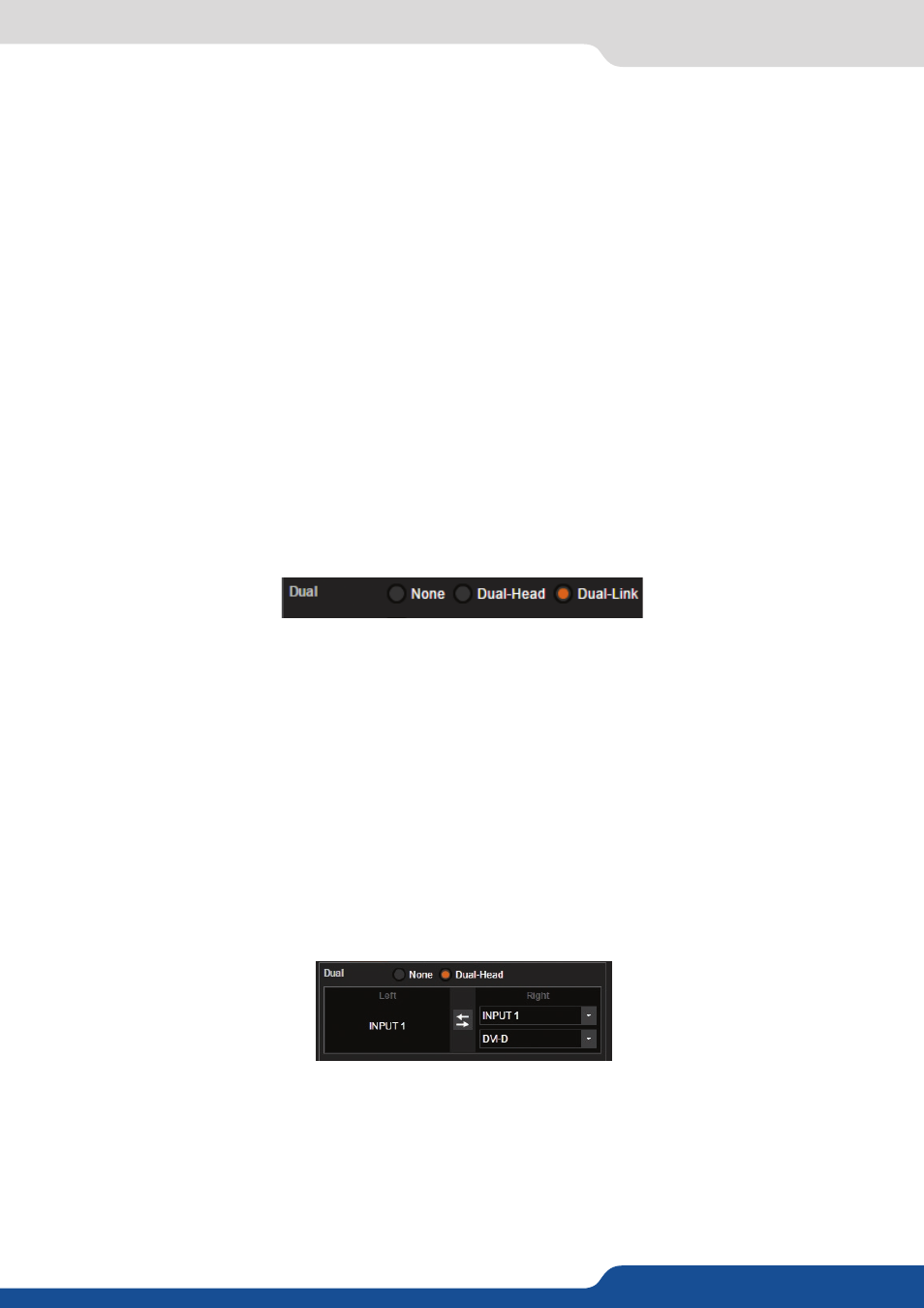
Under the input Setup menu, you can check the feature DUAL-HEAD of your inputs. You just need to indicate
which second plug is linked to the actual input. In this example, the input #2 is linked in Dual-Head with the
input #1 .