Beisler 1710-5 User Manual
Page 33
2-11
3.6
Setup page -10
M8
M7
M6
M5
M4
M3
M2
M1
F12
F11
F10
F9
F8
F7
F6
F5
F4
F3
F2
F1
SETUP
-10
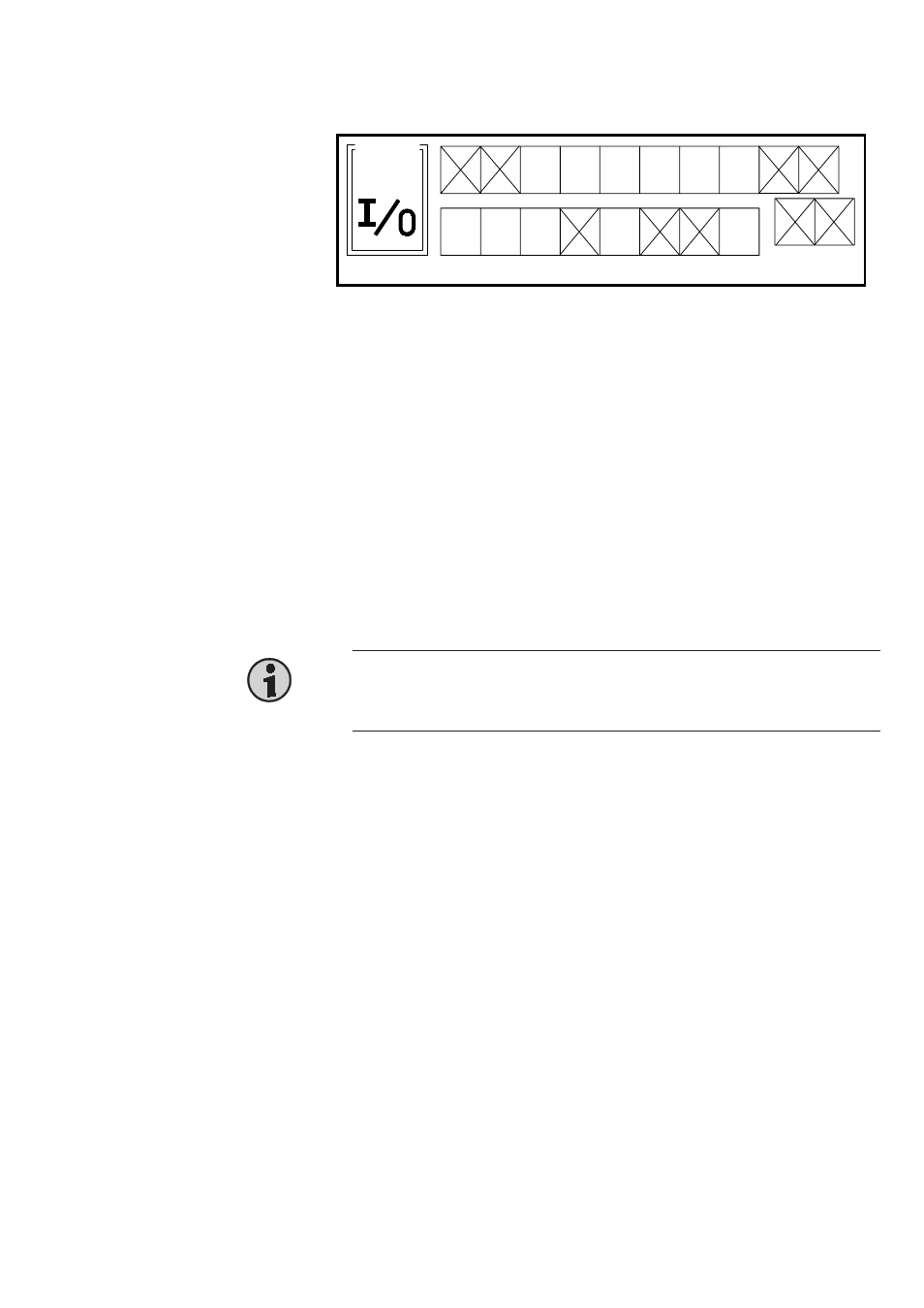
All inputs (F1 ... F12) and outputs (M1 ... M8) are displayed on this page. For
diabled inputs/outputs, the respective icon is crossed out.
At this machine, the output F1, F2 and F9 ... F12, and the inputs M4, M6 and
M7 must be disabled. Position the cursor on the icon of an input/output and
press the Plus/Minus key to alter the setting.
The outputs are valves and occupied as follows:
Valve description
Output connector
F1 Y1
Lift sewing foot and puller
pin 1
F3 Y3
Knife (Push valve)
pin 5
F4 Y4
Knife (Push valve)
pin 7
F5 Y5
Stacker stamp
pin 9
F6 Y6
Stacker transport
pin 11
F7 Y7
Slide table
pin 13
F8 Y8
Transportation belt down
pin 15
Hint
The output „Lift sewing foot and puller“ (Y1) cannot be programmed on Setup
page -10 and must be programmed on Setup page -03 (see there).
The inputs are occupied as follows:
Description
Input connector
M1 ES1
Start button
pin 2-4
M2 FZ3
Knife on and stacker start (photo cell)
pin 6-4
M3 FZ3
Knife on and stacker start
pin 8-10
M5 ES4
Initiator stacker transport in rear position
and slide table open
FZ2
Sewing stop;
pin 19 = -12 V, pin 20 = +12 V, switch output pin 18