Description of the demodulator, Overview, 7 description of the demodulator – Comtech EF Data SDM-300L3 User Manual
Page 30: 1 overview
SDM-300L3 Satellite Modem
Revision 1
Introduction
MN/SDM300L3.IOM
1–10
1.7
Description of the Demodulator
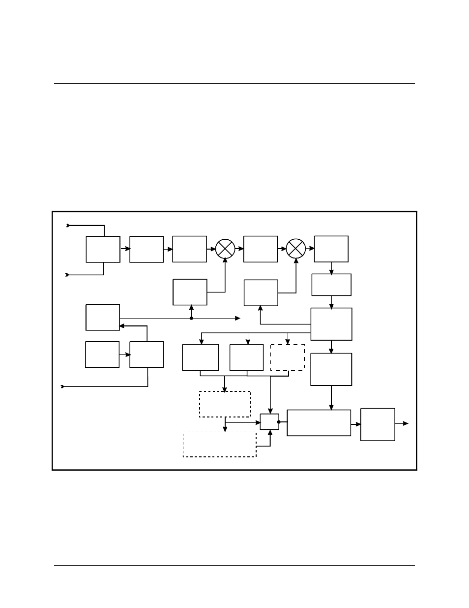
A block diagram of the demodulator is shown in Figure 1-2.
1.7.1
Overview
The demodulator converts PSK modulated carriers within the 950 to 1750 MHz range to
a demodulated baseband data stream. The converted modulation types are BPSK, QPSK,
OQPSK, and 8-PSK. The demodulator then performs FEC decoding on the data stream to
produce the error corrected data output to the data interface.
Figure 1-2
. Demodulator Block Diagram
DIGITAL
SIGNAL
PROCESSING
DIGITAL
CLOCK
RECOVERY-
LOOP
SWITCH
REF
VCXO
REF
PLL
OC XO
OPT
HIGH
STABILITY
AGC
LPF
BPF
LO #2
LOOPBACK
L-BAND INPUT
L-BAND INPUT
BPF
A TO D
CONVERTER
LO #1
REFERENCE
VITERBI
DECODER
SEQUENTIAL
DECODER
OPTIONAL
REED-SOLOMON
CODEC
DOPPLER/
PLESIOCHRONOUS
BUFFER
MUX
INTERFACE
OPTIONAL
OVERHEAD DEFRAMING
IBS/IDR, ASYNC/AUPC
DROP & INSERT
EXT REFERENCE
OPTIONAL
TURBO
CODEC