Entone Hydra II User Manual
Page 11
Hydra User’s Guide
Copyright
2007 Entone, Inc. All rights reserved
.
9
FRONT PANEL AND REAR PANEL
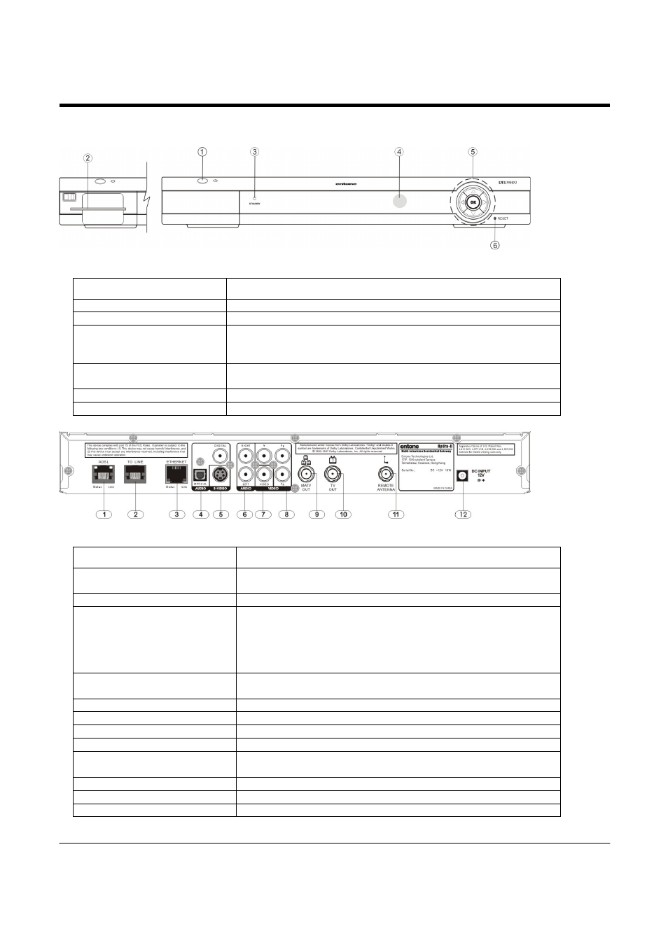
Figure 2-1 Hydra Front Panel
Part Name
Description
1. Standby Switch
Power up or put Hydra in standby mode
2. Smart Card Slot
Optional for conditional access authentication
3. Standby/On Indicator
Amber: standby mode and starting;
Green: when started
Red: in remote registration mode
4. IR receiver
Remote control IR receiver.
If the receiver is flashing Red/Green: upgrading software
5. Arrow Keys/OK Button
Usage determined by middleware
6. Reset Pin Hole
Restart Hydra
Figure 2-2 Hydra Rear Panel
Part Name
Description
1. ADSL
The ADSL RJ11 port is used to connect an ADSL line when the
Hydra's internal ADSL router is used.
2. TO LINE
RJ11 plug for connecting to telephone line for caller ID display
3. ETHERNET
1) This RJ45 port can function as the primary WAN connection
when the Hydra's internal ADSL router is not used.
2) When the internal ADSL router is used, this port provides a
data connection for PC's and other in-home networking
equipment.
4. OPTICAL AUDIO/DIGITAL
AUDIO
S/PDIF digital optical audio TOSLINK output for decoder 1
S/PDIF digital coaxial RCA audio output for decoder 1
5. S-VIDEO
S-Video output for decoder 1
6. AUDIO LEFT/RIGHT
Composite audio output for decoder 1
7. VIDEO
Composite video output for decoder 1
8. YPbPr
Component video output for decoder 1
9. MATV OUT
RF Type-F connector for decoder 1, 2 and 3 (factory set to channel
10, 12 and 23)
10. TV OUT
RF Type-F connector for decoder 1 (factory set to channel 10)
11. REMOTE ANTENNA
RF Type-F connector for connecting the RF remote control antenna
12. DC INPUT
12V DC power jack