4 installation, 1 location, 2 part assemblies – Flowserve S-series PolyChem User Manual
Page 14: 3 foundation
USER INSTRUCTIONS POLYCHEM S-SERIES ENGLISH 71569207 11-08
Page 14 of 52
flowserve.com
Figure 3-3A: Pressure-temperature rating
(ISO pump with PN 16 flanges – Material Group No. 1.0)
Temperature
°C ( °F)
-29
(-20)
-18
(0)
38
(100)
93
(200)
121
(250)
149
(300)
Bar
(psi)
16
(232)
16
(232)
16
(232)
16
(232)
16
(232)
15.5
(225)
Figure 3-3B: Pressure–temperature rating
(ANSI pump with Class 150 flanges – Material Group
No. 1.0)
Temperature
°C ( °F)
-29
(-20)
-18
(0)
38
(100)
93
(200)
149
(300)
Bar
(psi)
17.2
(250)
17.2
(250)
17.2
(250)
16.2
(235)
14.8
(215)
3.4.4 Minimum continuous flow
The minimum continuous flow (MCF) is based on a
percentage of the best efficiency point (BEP). Figure
3-4 identifies the MCF for all PolyChem S-series pumps.
Figure 3-4: Minimum continuous flow
MCF % of BEP
Pump size
3 500/2 900
r/min
1 750/1 450
r/min
1 180/960
r/min
PS3x2-6
20 %
10 %
10 %
PS3x2-10
PS50-250
30 %
10 %
10 %
PS4x3-10
PS65-250
n/a
10 %
10 %
PS3x2-13
PS50-315
n/a
10 %
10 %
PS4x3-13
PS65-315
n/a
20 %
10 %
PS6x4-13HD
PS100-315
n/a
40 %
10 %
All other sizes
10 %
10 %
10 %
4 INSTALLATION
Equipment operated in hazardous locations
must comply with the relevant explosion protection
regulatiuons. See section 1.6.4, Products used in
potentially explosive atmospheres.
4.1 Location
The pump should be located to allow room for access,
ventilation, maintenance, and inspection with ample
headroom for lifting and should be as close as
practicable to the supply of liquid to be pumped.
Refer to the general arrangement drawing for the
pump set.
4.2 Part assemblies
The supply of motors and baseplates are optional.
As a result, it is the responsibility of the installer to
ensure that the motor is assembled to the pump and
aligned as detailed in section 4.5 and 4.8.
4.3 Foundation
4.3.1 Protection of openings and threads
When the pump is shipped, all threads and all
openings are covered. This protection/covering
should not be removed until installation. If, for any
reason, the pump is removed from service, this
protection should be reinstalled.
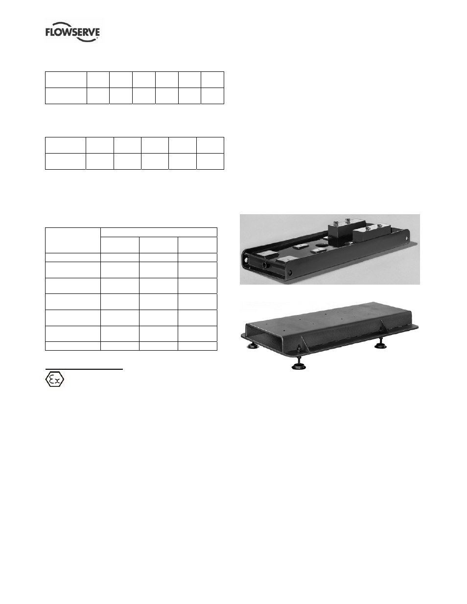
4.3.2 Rigid baseplates - overview
The function of a baseplate is to provide a rigid
foundation under a pump and its driver that maintains
alignment between the two. Baseplates may be
generally classified into two types:
• Foundation-mounted, grouted design. (Figure 4-1.)
• Stilt mounted, or free standing. (Figure 4-2.)
Figure 4-1
Figure 4-2
Baseplates intended for grouted installation are
designed to use the grout as a stiffening member.
Stilt mounted baseplates, on the other hand, are
designed to provide their own rigidity. Therefore the
designs of the two baseplates are usually different.
Regardless of the type of baseplate used, it must
provide certain functions that ensure a reliable
installation. Three of these requirements are:
• The baseplate must provide sufficient rigidity to
assure the assembly can be transported and
installed, given reasonable care in handling,
without damage. It must also be rigid enough
when properly installed to resist operating loads.
• The baseplate must provide a reasonably flat
mounting surface for the pump and driver.
Uneven surfaces will result in a soft-foot condition
that may make alignment difficult or impossible.