Flowserve S-series PolyChem User Manual
Page 28
USER INSTRUCTIONS POLYCHEM S-SERIES ENGLISH 71569207 11-08
Page 28 of 52
flowserve.com
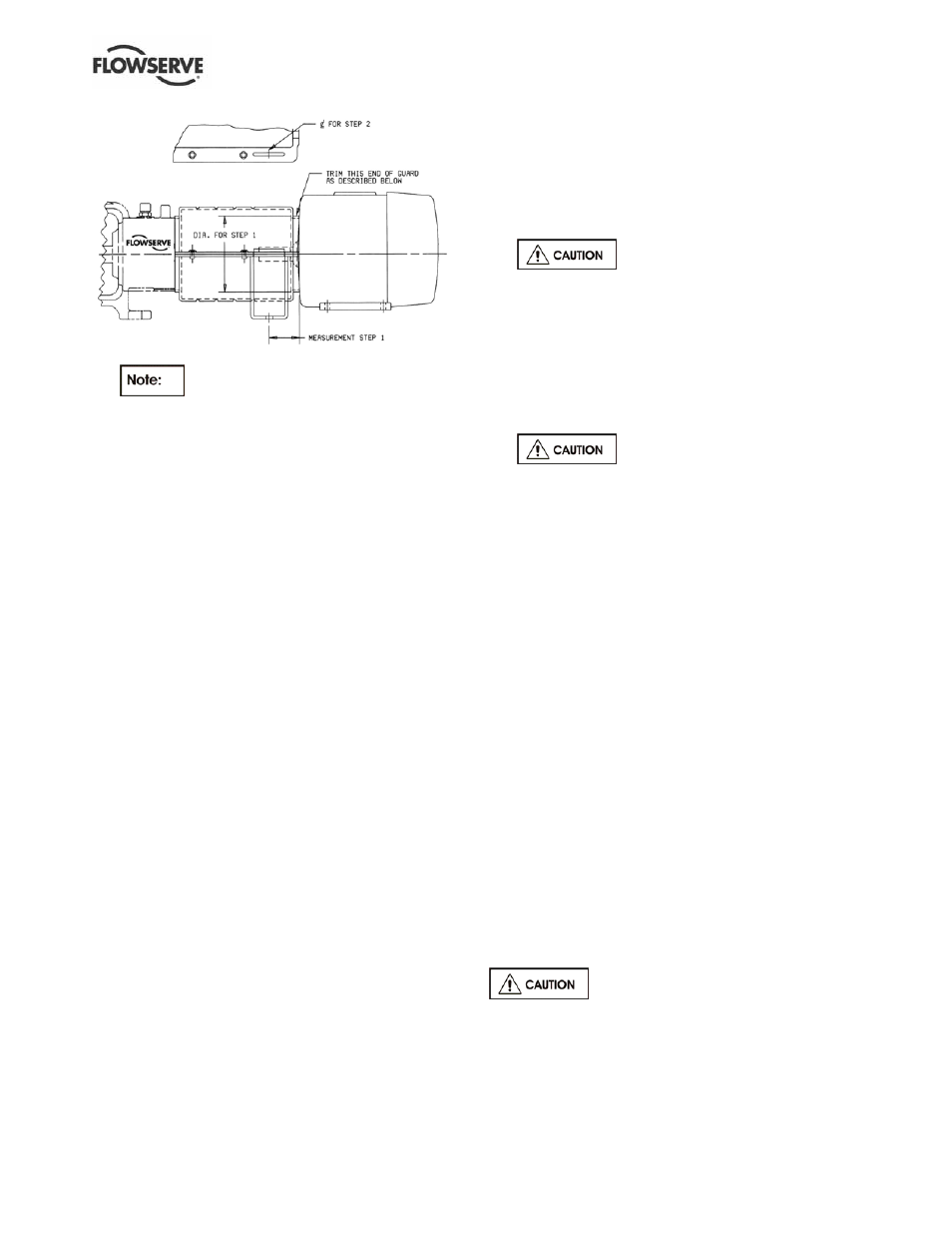
Figure 5-14
d)
If motor diameter is smaller than guard
diameter, trim guard so that it extends over the
end of the motor as far as possible.
e) Deburr the trimmed end with a file or a sharp
knife if ClearGuard™. Care must be taken to
eliminate all sharp edges.
5.5.4 Assembly instructions
5.5.4.1 Clam shell guard
a) Mount support leg to each clam shell, figure 5-12.
b) Attach one half of the guard to the baseplate.
c) Engage the tabs of guard halves together.
d) Attach the second support leg to the baseplate.
5.5.4.2 ClearGuard™
a) Place the bottom and top halves of the guard
around the coupling.
b) Install the support legs by inserting and then
rotating the tab on the leg through the slot in the
guard until it comes through and locks the top
and bottom halves of the guard together.
c) Attach the support legs to the baseplate using the
fasteners and washers provided.
d) Install fasteners in the holes provided to secure
the guard flanges together.
5.6 Priming and auxiliary supplies
The PolyChem S-series centrifugal pump will not move
liquid unless the pump is primed. A pump is said to be
“primed” when the casing and the suction piping are
completely filled with liquid. Open discharge valves a
slight amount. This will allow any entrapped air to
escape and will normally allow the pump to prime, if the
suction source is above the pump. When a condition
exists where the suction pressure may drop below the
pump’s capability, it is advisable to add a low-pressure
control device to shut the pump down when the
pressure drops below a predetermined minimum.
5.7 Starting the pump
a) Open the suction valve to full open position. It is
very important to leave the suction valve open while
the pump is operating. Any throttling or adjusting of
flow must be done through the discharge valve.
Partially closing the suction valve can create
serious NPSH and pump performance problems.
b)
Never operate pump with both the
suction and discharge valves closed. This could
cause an explosion.
c) Ensure the pump is primed. (See section 5.6.)
d) All cooling, heating, and flush lines must be
started and regulated.
e) Start the driver (typically, the electric motor).
f) Slowly open the discharge valve until the desired
flow is reached, keeping in mind the minimum
continuous flow listed in section 3.4.4.
g)
It is important that the discharge valve
be opened within a short interval after starting the
driver. Failure to do this could cause a dangerous
build up of heat, and possibly an explosion.
5.8 Running or operation
5.8.1 Minimum continuous flow
Minimum continuous stable flow is the lowest flow at
which the pump can operate and still meet the bearing
life, shaft deflection and bearing housing vibration limits
documented in the latest version of ASME B73.1.
Pumps may be operated at lower flows, but it must be
recognized that the pump may exceed one or more of
these limits. For example, vibration may exceed the
limit set by the ASME standard. The size of the pump,
the energy absorbed, and the liquid pumped are some
of the considerations in determining the minimum
continuous flow (MCF).
The minimum continuous flow (capacity) is established
as a percentage of the best efficiency point (BEP). (See
section 3.4.4.)
5.8.2 Minimum thermal flow
All PolyChem S-series pumps also have a minimum
thermal flow. This is defined as the minimum flow
that will not cause an excessive temperature rise.
Minimum thermal flow is application dependent.
Do not operate the pump below
minimum thermal flow, as this could cause an excessive
temperature rise. Contact a Flowserve sales engineer
for determination of minimum thermal flow.