Flowserve S-series PolyChem User Manual
Page 36
USER INSTRUCTIONS POLYCHEM S-SERIES ENGLISH 71569207 11-08
Page 36 of 52
flowserve.com
Design 3 standard is a carbon filled fluoropolymer
sleeve. Depending on the seal design, if set screws
are utilized to attach the rotary unit and they fall onto
the sleeve, damage may occur. You may wish to
convert to Design 2.
Sleeve design 1 and 2
d) Remove the seal gland nuts [6580.2] if so
equipped.
e) Remove the two cap screws [6570.2] which
attach the rear cover [1220] to the adapter.
Carefully remove this part.
f)
If a component type inside mechanical seal [4200]
is used, loosen the set screws on the rotating unit
and remove it from the shaft. Then pull the gland
[4120] and the stationary seat off the shaft.
Remove the stationary seat from the gland.
g) If a component type outside mechanical seal is
used, remove the gland [4120] and the stationary
seat. Remove the stationary seat from the gland.
Loosen the set screws in the rotating unit and
remove it from the shaft.
h) Discard all O-rings and gaskets.
i)
If the pump has a sleeve [2400] it can now be
removed. The unit now appears as shown in
Figure 6-7. Proceed to step j).
Figure 6-7
Sleeve design 3
d) Remove the sleeve [2400]. The use of a gear
puller may be necessary since the sleeve is
mounted on tolerance rings. (See Figure 6-8.)
Discard tolerance rings.
Figure 6-8
e) Remove the two cap screws [6570.2] which
attach the rear cover [1220] to the adapter.
Carefully remove this part.
f) Remove the seal gland nuts [6580.2]. Proceed to
step j).
j)
If the power end is oil lubricated, remove the
drain plug [6569.1] and drain the oil from the
bearing housing [3200].
k) If the pump has lip seals, a deflector [2540] will
be present. Remove it.
l)
Loosen the three set screws [6570.3] on the
bearing carrier [3240]. The bearing carrier must be
completely unscrewed from the bearing housing.
Do not pry against the shaft.
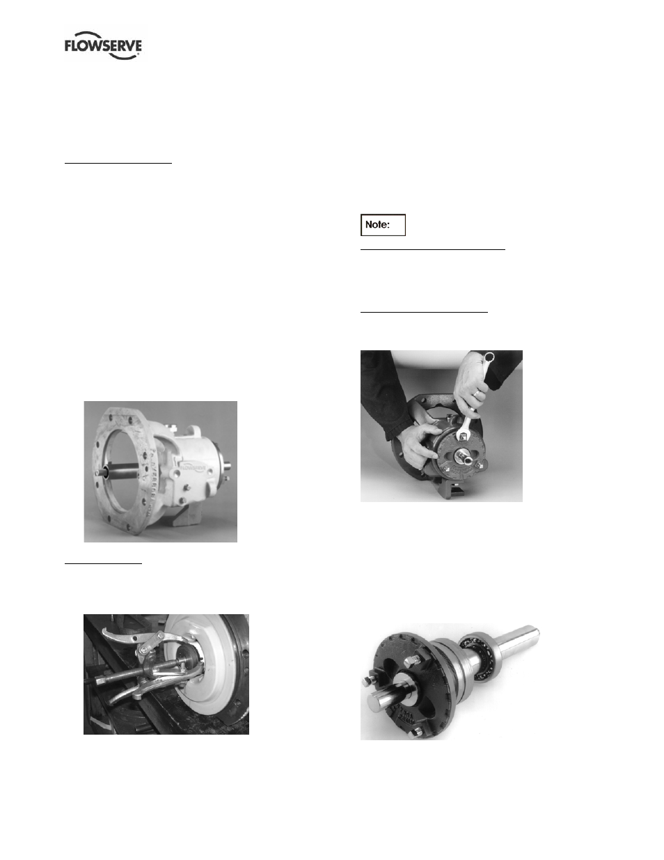
ISO Group A and ANSI pumps:
The face of the bearing carrier has three square
lugs that protrude from the surface. The bearing
carrier is turned by using an open end wrench on
one of the square lugs as shown in Figure 6-9.
ISO Group B and C pumps:
The bearing carrier is turned by using a strap
wrench, with the strap located around the outside
diameter of the carrier face.
Figure 6-9
m) Because the O-rings [4610.2] will cause some
resistance in removing the bearing carrier
assembly from the housing, hold the bearing
carrier flange firmly and with slight rotation, pull it
out of the bearing housing. The bearing carrier
assembly with the shaft and bearings should
come free. This unit will appear as shown in
Figure 6-10. Further disassembly is not required
unless the bearings are to be replaced.
Figure 6-10
n) Remove the snap ring [2530]. (See Figure 6-11.)