Flowserve S-series PolyChem User Manual
Page 40
USER INSTRUCTIONS POLYCHEM S-SERIES ENGLISH 71569207 11-08
Page 40 of 52
flowserve.com
This will cause the gland to cock, which causes the
stationary seat to be cocked, which causes the seal
to wobble. This run-out should be less than 0.08 mm
(0.003 in.) and should be measured as shown below:
Face squareness
Register concentricity
An eccentric seal chamber bore or gland register can
interfere with the piloting and centering of the seal
components and alter the hydraulic loading of the seal
faces, resulting in reduction of seal life and
performance. The seal chamber register concentricity
should be less than 0.13 mm (0.005 in.). The diagram
below shows how to measure this concentricity.
Concentricity
6.9.4.7 Installed pump
Complete pump installed.
Shaft movement caused by pipe strain
Pipe strain is any force put on the pump casing by the
piping. Pipe strain should be measured as shown
below. Install the indicators as shown before
attaching the piping to the pump. The suction and
discharge flanges should now be bolted to the piping
separately while continuously observing the
indicators. Indicator movement should not exceed
0.05 mm (0.002 in.).
Pipe strain movement
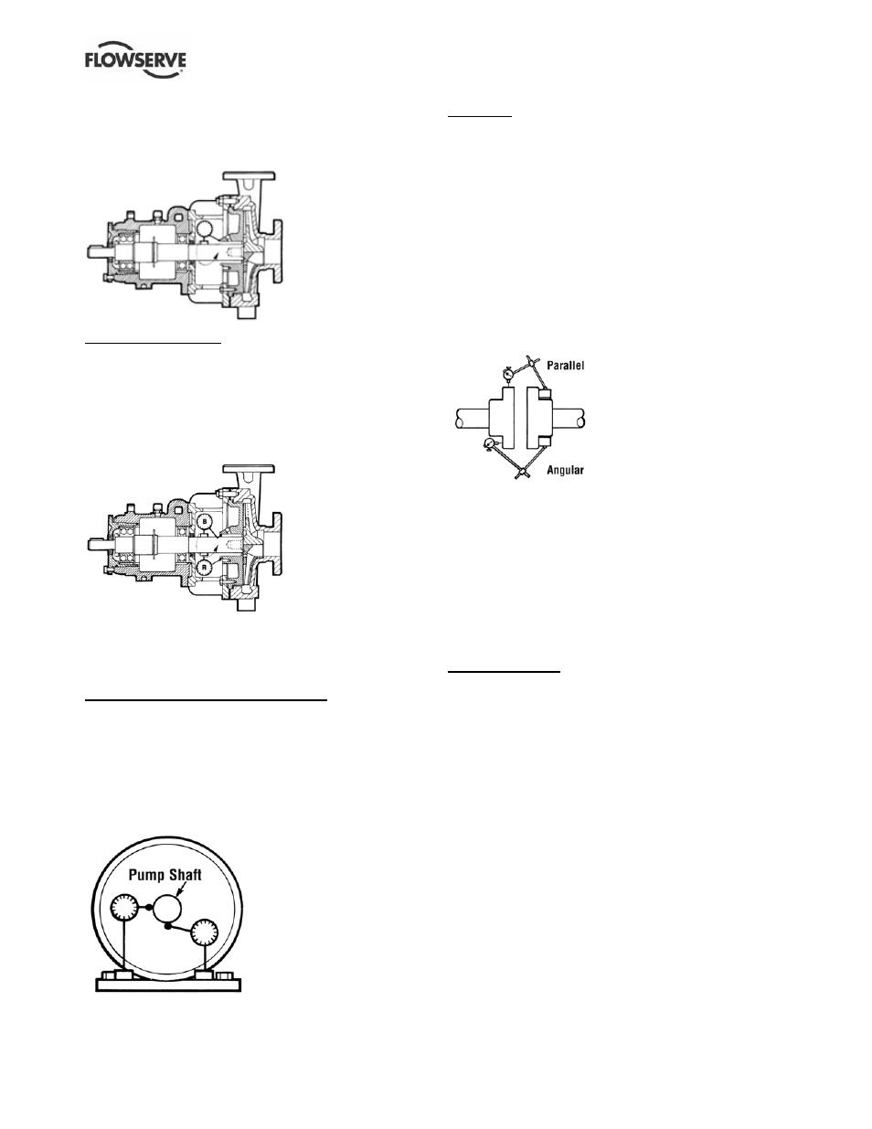
Alignment
Misalignment of the pump and motor shafts can
cause the following problems:
• Failure of the mechanical seal
• Failure of the motor and/or pump bearings
• Failure of the coupling
• Excessive
vibration/noise
The schematics below show the technique for a
typical rim and face alignment using a dial indicator.
It is important that this alignment be done after the
flanges are loaded, and at typical operating
temperatures. If proper alignment cannot be
maintained a C-flange motor adapter and/or
stilt/spring mounting should be considered.
Alignment
Many companies today are using laser alignment
which is a more sophisticated and accurate
technique. With this method a laser and sensor
measure misalignment. This is fed to a computer
with a graphic display that shows the required
adjustment for each of the motor feet.
See section 4.8 for recommended final shaft
alignment limits.
Vibration analysis
Vibration analysis is a type of condition monitoring
where a pump’s vibration “signature” is monitored on
a regular, periodic basis. The primary goal of
vibration analysis is extension on MTBPM. By using
this tool Flowserve can often determine not only the
existence of a problem before it becomes serious, but
also the root cause and possible solution.
Modern vibration analysis equipment not only detects if a
vibration problem exists, but can also suggest the cause
of the problem. On a centrifugal pump, these causes can
include the following: unbalance, misalignment, defective
bearings, resonance, hydraulic forces, cavitation and
recirculation. Once identified, the problem can be
corrected, leading to increased MTBPM for the pump.
Flowserve does not make vibration analysis equipment,
however Flowserve strongly urges customers to work
with an equipment supplier or consultant to establish an
on-going vibration analysis program. See note 3 under
Figure 6-13 regarding acceptance criteria.