Flowserve S-series PolyChem User Manual
Page 22
USER INSTRUCTIONS POLYCHEM S-SERIES ENGLISH 71569207 11-08
Page 22 of 52
flowserve.com
Figure 4-16: Maximum Z-axis loading for shaft deflection
Suction Discharge
Forces N (lbf)
Moments Nm (lbf•ft)
Forces N (lbf)
Moments Nm (lbf•ft)
Pump size
Fxs Fys Fzs Mxs Mys Mzs Fxd Fyd Fzd Mxd Myd Mzd
Grupo 1 & A
4 670
(1 050)
-
-5 560
(-1 250)
2 034
(1 500)
1 627
(1 200)
-3 390
(-2 500)
3 558
(800)
8 896
(2 000)
-13 344
(-3 000)
-2 034
(-1 500)
1 356
(1 000)
-3 390
(-2 500)
Grupo 2, B & C
15 568
(3 500)
-
-6 672
(-1 500)
2 034
(1 500)
1 763
(1 300)
-4 746
(-3 500)
6 227
(1 400)
11 120
(2 500)
-14 456
(-3 250)
-2 034
(-1 500)
2 915
(2 150)
-4 746
(-3 500)
4.6.5 Pump and shaft alignment check
After connecting the piping, rotate the pump drive
shaft clockwise (viewed from motor end) by hand
several complete revolutions to be sure there is no
binding and that all parts are free. Recheck shaft
alignment. (See section 4.5.) If piping caused unit to
be out of alignment, correct piping to relieve strain on
the pump.
4.6.6 Auxiliary piping
4.6.6.1 Mechanical seal
When the pump is intended to be equipped with a
mechanical seal, it is Flowserve standard practice to
install the mechanical seal in the pump prior to
shipment. Specific order requirements may specify
that the seal be shipped separately, or none be
supplied. It is the pump installer’s responsibility to
determine if a seal was installed. If a seal was
supplied but not installed, the seal and installation
instructions will be shipped with the pump.
Failure to ensure that a seal is installed
may result in serious leakage of the pumped fluid.
Seal and seal support system must be installed and
operational as specified by the seal manufacturer.
The seal chamber/gland may have ports that have
been temporarily plugged at the factory to keep out
foreign matter. It is the installer’s responsibility to
determine if these plugs should be removed and
external piping connected. Refer to the seal
drawings and or the local Flowserve representative
for the proper connections.
4.6.6.2 Piping connection – seal support system
If the pump has a seal support system
it is mandatory that this system be fully installed and
operational before the pump is started.
4.6.6.3 Piping connection - bearing housing
cooling system
Make connections as shown below. Liquid at less
than 32 °C (90 °F) should be supplied at a regulated
flow rate of at least 0.06 l/s (1 US gpm).
Figure 4-17
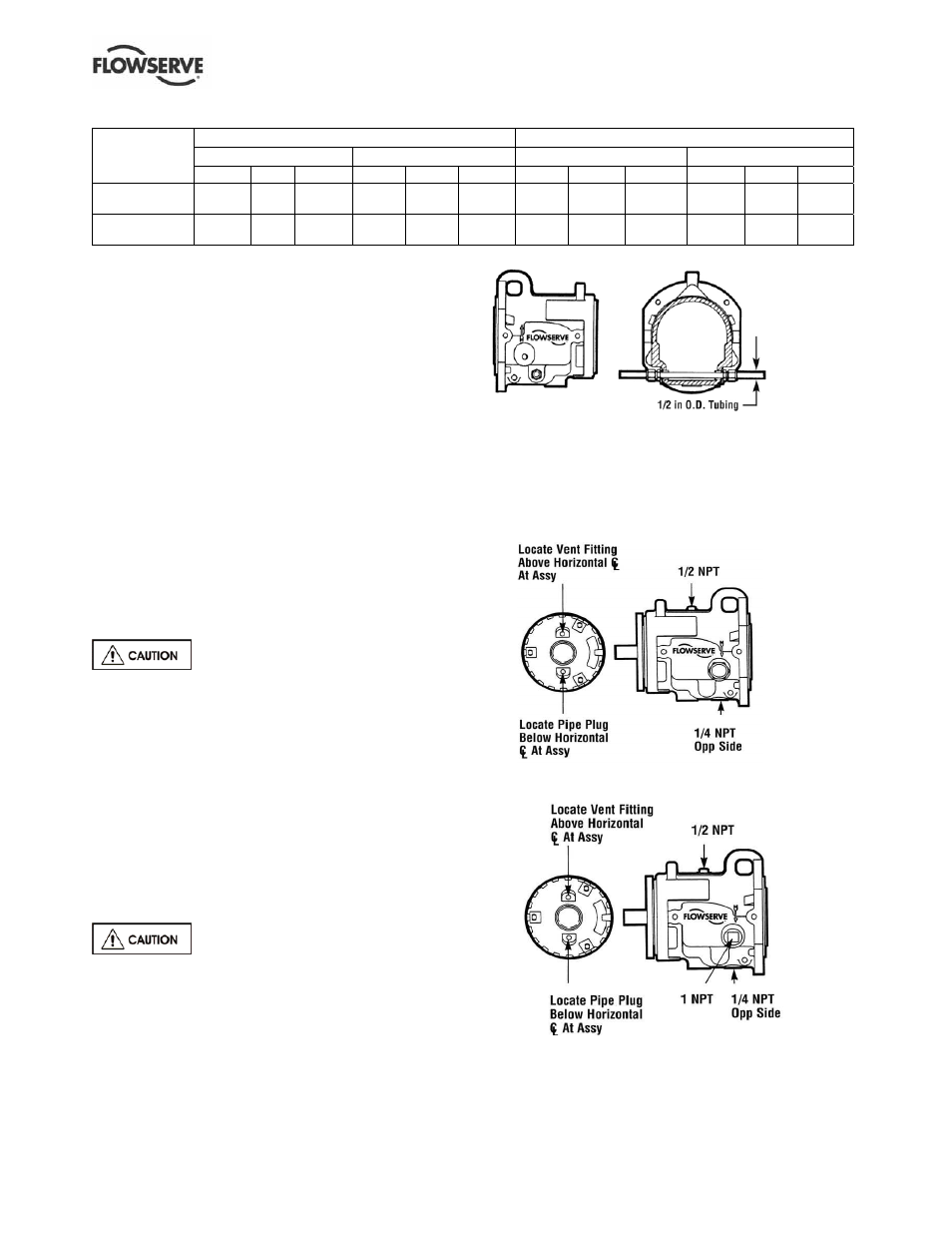
4.6.6.4 Piping connection - oil mist lubrication
system
The piping connections for an oil mist lubrication
system are shown below.
Figure 4-18: Oil mist ready housing wet sump
Figure 4-19: Oil mist ready housing dry sump