Flowserve S-series PolyChem User Manual
Page 42
USER INSTRUCTIONS POLYCHEM S-SERIES ENGLISH 71569207 11-08
Page 42 of 52
flowserve.com
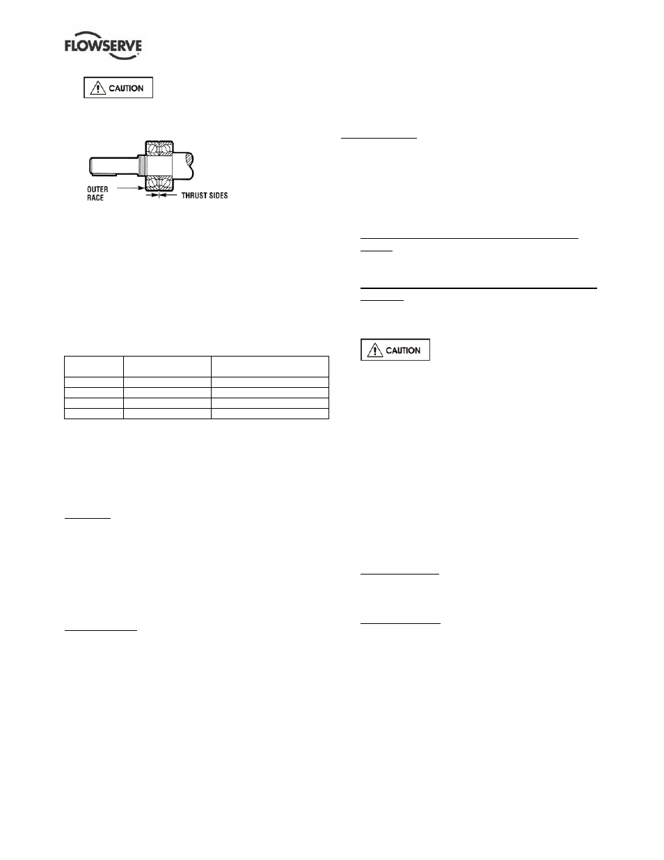
It must be understood that fixtures
and equipment used to press the bearing must be
designed so no load is ever transmitted through the
bearing balls. This would damage the bearing.
Figure 6-17
d) After the bearing has cooled below 38 °C (100 °F)
the bearing should be pressed against the shaft
shoulder. Figure 6-18 identifies the approximate
force needed to seat the bearing against the shaft
shoulder. If a press is not available the locknut
[3712] should be installed immediately after the
bearing is placed on the shaft and tightened to
ensure the bearing remains in contact with the shaft
shoulder. The locknut should then be retightened
repeatedly during the time the bearing is cooling.
Once cool the locknut should be removed.
Figure 6-18
Pump
Press force
N (lbf)
Locknut torque
Nm (lbf▪ft)
Group A/1
5 780 (1 300)
27 +4/-0 (20 +5/-0)
Group 2
11 100 (2 500)
54 +7/-0 (40 +5/-0)
Group B
9 600 (2 200)
46 +7/-0 (34 +5/-0)
Group C
12 000 (2 700)
63 +7/-0 (47 +5/-0)
e) Install lock washer [6541.1] and locknut [3712].
The locknut should be torqued to the value shown
in Figure 6-18. One tang on the lock washer must
be bent into a corresponding groove on the locknut.
6.10.1.2 Bearing housing seals
Lip seals. If lip seals were used, install new lip seals
in the bearing carrier [3240] and the housing [3200 -
Group A and 1] or the adapter [1340 - Group B, C
and 2]. The lip seals [4310.1 and 4310.2] are double
lip style, the cavity between these two lips should be
1
/
2
to
2
/
3
filled with grease. When installing this part,
the large metal face on the lip seal must face away
from the bearings.
Labyrinth seals. The following are general installation
instructions regarding the VBXX Inpro seal. Follow the
instructions provided with the seal by the manufacturer.
The elastomer O-ring located on the OD of the seal has
been sized to overfill the groove in which it is located.
When installing the seal into its corresponding housing,
in addition to compressing the O-ring a certain amount
of material may shear off. This sheared material should
be removed. An arbor press should be used to install
the seal. Install the inboard seal in the bore of the
bearing housing (Group A and 1) or adapter (Group B,
C and 2) with the single expulsion port positioned at the
6 o’clock position.
Install the outboard seal in the bore of the bearing
carrier. There are no orientation issues since this is a
multiport design seal.
Magnetic seals. Follow the installation instructions
provided by the manufacturer.
6.10.1.3 Bearing carrier/power end assembly
a) Install new O-rings [4610.2] onto the bearing carrier.
b) Slide the bearing carrier [3240] over the outboard
bearing [3013].
c) Install the outboard bearing retaining device.
Double row bearings on Group A, B, C, 1 and 2
pumps. Slide the snap ring [2530] in place with
its flat side against the outboard bearing and
snap it into its groove in the bearing carrier.
Duplex angular contact bearings on Group A, 1 and
2 pumps. Slide the bearing retainer [2530.1]
against the outboard bearing and install and
tighten the socket head cap screws [6570.12].
(See Figure 6-2 for correct torque values.)
Never compress the snap ring
unless it is positioned around the shaft and between
the bearings. In this configuration, it is contained
therefore if it should slip off the compression tool it
is unlikely to cause serious injury.
d) The shaft, bearings, and bearing carrier
assembly (Figure 6-10) can now be installed into
the bearing housing [3200]. The bearing carrier
[3240] should be lubricated with oil on the O-rings
and threads before installing the assembly into
the bearing housing. Thread the bearing carrier
into the bearing housing by turning it clockwise to
engage the threads. Thread the carrier onto the
housing until the carrier flange is approximately
3 mm (
1
/
8
in.) from the housing. Install the set
screws [6570.3] loosely.
e) Reinstall any tags, plugs, site gauges and oiler.
Mark 3A design. Install the following items onto
the bearing housing; oil level tag (Figure 6-12)
and combination Trico oiler/sight gauge [3855],
vent/ breather [6521] and drain plug [6569.1].
ANSI 3A design. Install the following items onto
the bearing housing; oil level tag (Figure 6-12)
and sight gauge [3855], plug [6521] and magnetic
drain plug [6521.1].
f) On Group B, C and 2 pumps, assemble the
bearing housing adapter [1340] to the bearing
housing [3200]. Be sure to install a new O-ring
[4610.2]. Thread the cap screws [6570.5]
through the adapter and into the tapped holes in
the bearing housing.
g) If the pump has lip seals, install the deflector [2540].