Flowserve S-series PolyChem User Manual
Page 27
USER INSTRUCTIONS POLYCHEM S-SERIES ENGLISH 71569207 11-08
Page 27 of 52
flowserve.com
If maintenance work has been carried
out to the sites electrical supply, the direction of
rotation should be re-checked as above in case the
supply phasing has been altered.
Figure 5-11
5.4.2 Coupling installation
The coupling should be installed as
advised by the coupling manufacturer. Pumps are
shipped without the spacer installed. If the spacer
has been installed to facilitate alignment, then it must
be removed prior to checking rotation. Remove all
protective material from the coupling and shaft before
installing the coupling.
5.5 Guarding
Power must never be applied to the
driver when the coupling guard is not installed.
Flowserve coupling guards are safety devices intended
to protect workers from inherent dangers of the rotating
pump shaft, motor shaft and coupling. It is intended to
prevent entry of hands, fingers or other body parts into a
point of hazard by reaching through, over, under or
around the guard. No standard coupling guard provides
complete protection from a disintegrating coupling.
Flowserve cannot guarantee their guards will
completely contain an exploding coupling.
5.5.1 Clam shell guard - standard
The standard coupling guard for all PolyChem S-series
pumps is the “clam shell” design and is shown in Figure
5-12. It is hinged at the top and it can be removed by
loosening one of the foot bolts and sliding the support
leg out from under the cap screw (note that the foot is
slotted). The leg can then be rotated upward and half of
the guard can be disengaged (unhinged) from the other.
Only one side of the guard needs to be removed. To
reassemble simply reverse the above procedure.
Figure 5-12
The coupling guard shown in Figure 5-12 conforms to
the USA standard ASME B15.1, “Safety standard for
mechanical power transmission apparatus.”
Flowserve manufacturing facilities worldwide conform
to local coupling guard regulations.
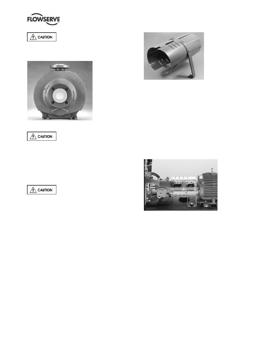
5.5.2 ClearGuard™ - optional
Flowserve offers as an option a ClearGuard™, which
allows you to see the condition of the coupling. (See
Figure 5-13.) This guard can be used in place of the
existing clamshell guard described above.
Disassembly of the ClearGuard™ is accomplished by
removing the fasteners that hold the two guard halves
together followed by removing the foot bolts and
rotating the support leg out of the slot on the guard.
Figure 5-13
5.5.3 Trimming instructions
In order to correctly fit the pump/motor configuration,
each guard must be trimmed to a specific length.
This trimming is done on the motor end of the guard.
a) Measure minimum distance from the center of
mounting hole in the baseplate to the motor.
(If clam shell guard proceed to step c.)
b) Locate a reference center in the slot of the
ClearGuard™ coupling guard flange, see figure
5-14. Transfer the length measurement to the
guard using this reference center.
c) Trim the motor end of the guard according to the
above measurement. Trimming is best done with
a band saw, but most other types of manual or
power saws give acceptable results. Care must
be taken to ensure that there is no gap larger
than 6 mm (0.24 in.) between the motor and the
coupling guard.