Flowserve S-series PolyChem User Manual
Page 45
USER INSTRUCTIONS POLYCHEM S-SERIES ENGLISH 71569207 11-08
Page 45 of 52
flowserve.com
e) Locate the rotary seal unit onto the shaft (or sleeve)
according to the set dimension provided by the seal
manufacturer. Tighten set screws on the seal to
lock the rotating unit to the shaft/sleeve.
f) Install the rear cover plate [1220] to the bearing
housing (Group A and 1) or the bearing housing
adapter (Group B, C, and 2) by using the cap
screws [6570.2].
g) Inset the pilot diameter of the stationary seat into
the seal chamber bore of the rear cover [1220].
h) Pilot the gland onto the seat using studs [6572.2]
and nuts [6580.2].
Single external seal installation
Carry out steps a) to c), above.
d) Locate the rotary seal unit onto the shaft/sleeve
according to the set dimension provided by the
seal manufacturer. Tighten set screws on the
seal to lock the rotating unit to the shaft/sleeve.
e) Install the gland gasket [4590.3], stationary seat
and a second gland gasket [4590.3] followed by
the gland [4120] onto the rear cover plate [1220].
f) Assemble using studs [6572.2] and nuts [6580.2].
g) Install the rear cover plate [1220] to the bearing
housing (Group A and 1) or the bearing housing
adapter (Group B, C, and 2) by using the cap
screws [6570.2].
Double seal installation
The PolyChem S-series pump line only has one rear
cover plate [1220] design (FML) therefore a canister
[1220.2] must be utilized to create a seal chamber in
which the inside stationary seat can be located.
Carry out steps a) to c), above.
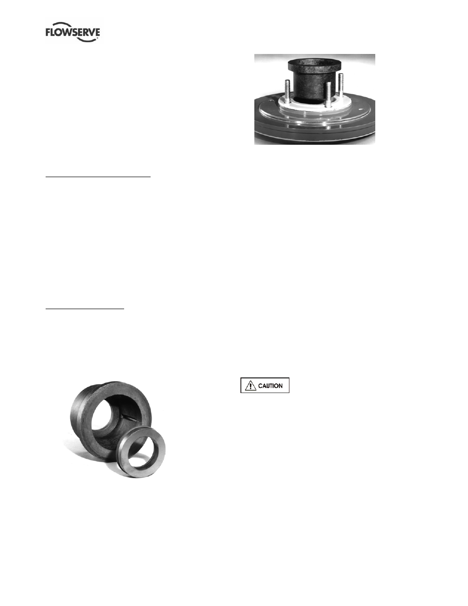
d) Install the inboard stationary seat into the canister
[1220.2]. (See Figure 6-26.)
Figure 6-26
e) Place a gland gasket [4590.3] onto the canister
[1220.2] and install this assembly into the rear
cover plate [1220]. (See Figure 6-27.)
f)
Install the outboard stationary seat into the gland
[4120] and place it onto the shaft until it lightly
touches the bearing housing (Group 1) or adapter
(Group 2 and 3).
Figure 6-27
g) Install a gland gasket [4590.3] into the gland.
h) Locate the rotary seal unit onto the shaft/sleeve
according to the set dimension provided by the seal
manufacturer. Tighten set screws on the seal to
lock the rotating unit to the shaft/sleeve. Install a
stationary seat into the rear cover plate [1220].
i)
Install the rear cover plate [1220] to the bearing
housing (Group A and 1) or the bearing housing
adapter (Group B, C and 2) by using the cap
screws [6570.2].
j)
Attach the gland/seat to the rear cover plate
[1220] using studs [6572.2] and nuts [6580.2].
6.10.3 Impeller assembly
The impeller [2200] can now be installed as instructed
in section 6.7. Remember that the impeller clearance
is already set. It cannot be changed at this point
without resetting the seal.
If a new impeller of maximum diameter has been
acquired and needs trimming or if the existing impeller
needs trimming this is accomplished by turning
(machining). It is recommended that this trimming
operation be performed by a Flowserve representative.
However, if this cannot be accommodated the following
guidelines should be followed.
Closed vane impellers are fully
trimable with the exception of the below noted pump
model. Open vane impellers are manufactured using
numerous component cores. See the chart below for
minimum trim ranges.
a) Obtain a machining arbor from a Flowserve
representative or use the pump shaft.
b) Carefully mount the arbor or shaft into a lathe.
Take care to minimize the runout of the machining
arbor/shaft.
c) Install the impeller.
d) All impellers trims are machined straight (parallel
to the pump shaft).