Gasboy Atlas Start-up User Manual
Page 76
Advertising
Page 5-16
MDE-4334D Atlas™ Start-up and Service Manual · July 2013
Electronic and Electrical Components
PCAs
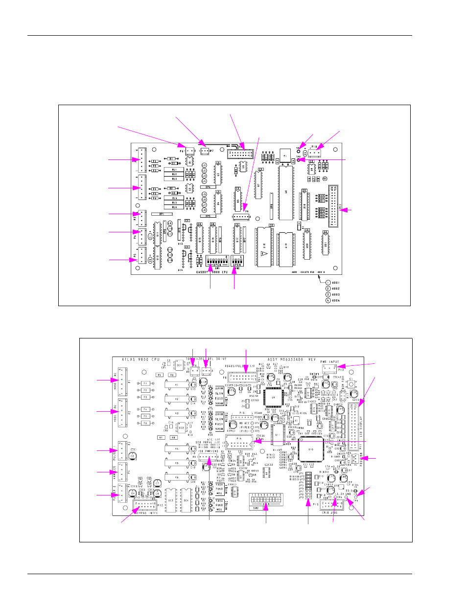
shows the previous Atlas 9800K CPU.
Figure 5-7: M05346A002 (115 VAC) and M05346A004 [230 VAC (Previous Atlas 9800K
CPUs)]
TP1
P6 (Totalizer)
P7 (Relay Drive)
P8 (RS-485/Pulser I/F)
P10 (Power Input)
P11 (LCD Display)
Switch 1
Switch 2
TP2
P1 (Hose 1 AC)
P2 (Hose 2 AC)
P3 (Pulser 1)
P4 (Handles)
P5 (Pulser 2)
P9 (ISB PWR/GND)
Figure 5-8: Current Atlas 9800 CPU (M06333KXXXX)
P10
P11
P14
(Serial
Peripheral I/F)
JP 1-9
SW2, 1-10
P12 (Not Used)
P5
P4
P3
P2
P1
P6
P7
P8
P9
TP4
(+3.3 V)
TP5
(GND)
TP6
(+5 V)
P18
Note: For cable block diagram, refer to M05193.
Advertising